Parameter List and Menu Structure of VS 300
148
Doku-Version 2.05 - Firmware 2.10 - 15. September 2017
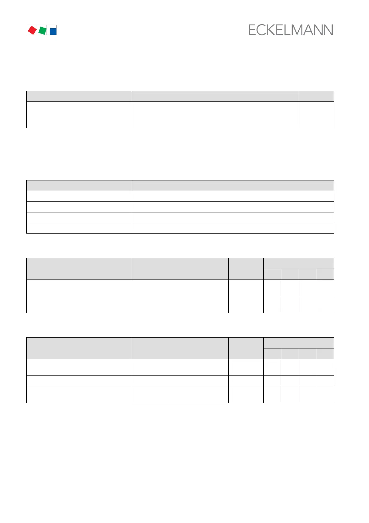
8.4.8 Menu 7 Basic Settings
VS 300 POS: XXXXX Entry
Load default
Are you sure ?
No: ESC Yes: ↵
Safety prompt for loading basic settings
ESC, ↵
8.4.9 Menu 8 Service Mode
SERVICE POS: XXXXX
1 Analog Values Next: Screen 8-1
2 Compressor/Cond. fan CL1 Next: Screen 8-2
3 Compressor/Cond. fan CL2 Next: Screen 8-3
4 System Next: Screen 8-4
S Menu 8-1 Analog Values
SERVICE POS: XXXXX Entry
Default
NT LT HP Dim.
AnalogOut1 XX.XV Voltage at analog output 1 ↑, ↓
(0,0 - 10,0)
0.0 0.0 0.0 V
AnalogOut2 XX.XV Voltage at analog output 2 ↑, ↓
(0,0 - 10,0)
0.0 0.0 0.0 V
S Menu 8-2 Compressors/Fans CL1
SERVICE POS: XXXXX Entry
Default
NT LT HP Dim.
Stage 1 XXX Actuating state compressor/fan stage 1
1)
↑, ↓
(ON/OFF)
OFF OFF OFF -
...
Stage 12 XXX Actuating state compressor/fan stage 12
1)
↑, ↓
(ON/OFF)
OFF OFF OFF -
1)
Number of relay/control stages CL1 [1..n] + Number of relays CL2 [n+1..m] + Number internal alarm relais
<= Number of relay/control stages VS 300 (max. 4, 8, 12 depending on expansion stage and configuration);
see section 4.1.1 System Configuration - Allocation of Relay/Control Stages