Parameter List and Menu Structure of VS 300
149
Doku-Version 2.05 - Firmware 2.10 - 15. September 2017
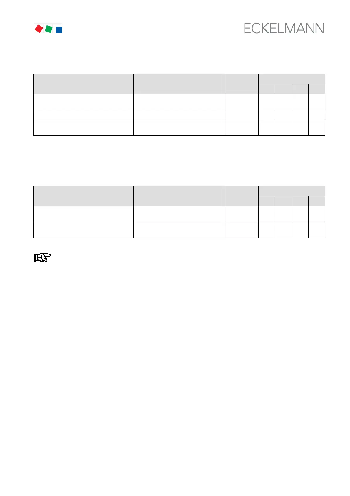
S Menu 8-3 Compressors/Fans CL2
SERVICE POS: XXXXX Entry
Default
NT LT HP Dim.
Stage 1 XXX Actuating state compressor/fan stage 1
1)
↑, ↓
(ON/OFF)
OFF OFF OFF -
...
Stage 12 XXX Actuating state compressor/fan stage 12
1)
↑, ↓
(ON/OFF)
OFF OFF OFF -
1)
Number of relay/control stages CL1 [1..n] + Number of relays CL2 [n+1..m] + Number internal alarm relais
<= Number of relay/control stages VS 300 (max. 4, 8, 12 depending on expansion stage and configuration);
see section 4.1.1 System Configuration - Allocation of Relay/Control Stages
S Menu 8-4 System
SERVICE POS: XXXXX Enry
Default
NT LT HP Dim.
Alarm-Output 3/7/11
1)
XXX Actuating state alarm output 1
3/7/11
1)
↑, ↓
(ON/OFF)
OFF OFF OFF -
Alarm-Output 4/8/12
1)
XXX Actuating state alarm output 2
4/8/12
1)
↑, ↓
(ON/OFF)
OFF OFF OFF -
This screen is only displayed when the VS 300 is configured with an internal alarm relay (1 or 2)!
1)
see section 4.1.1 System Configuration - Allocation of Relay/Control Stages