Parameter List and Menu Structure of VS 300
122
Doku-Version 2.05 - Firmware 2.10 - 15. September 2017
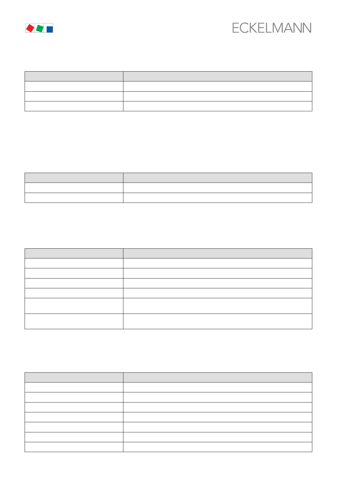
S Menun 2-3 Compressor/Fans Control Loop 2
CL2-COMP./COND POS: XXXXX
Stage 1 XXX Display ON/OFF: Actuating status of digital output, relay/control stagee 1
... Only actual number of compressor/fans in Control Loop 2 is shown
Stage 12 XXX Display ON/OFF: Actuating status of digital output, relay/control stage 12
1)
1)
First relay/control stage of Control Loop 2 directly follows last stage of Control Loop 1. Position of first
relay/control stage of Control Loop 2 is accordingly determined by control loop configuration.
Number of relay/control stages CL1 [1..n] + Number of relays CL2 [n+1..m] + Number internal alarm relay
<= Number of relay/control stages VS 300 (max. 4/8/12 depending on expansion stage and configuration),
see section 4.1.1 System Configuration - Allocation of Relay/Control Stages
S Menu 2-4 Internal Alarm
INT ALARM POS: XXXXX
Stage 1 Display ON/OFF: Actuating status of digital alarm output 1
Stage 2 Display ON/OFF: Actuating status of digital alarm output 2
Number of relay/control stages CL1 [1..n] + Number of relays CL2 [n+1..m] + Number internal alarm relay
<= Number of relay/control stages VS 300 (max. 4/8/12 depending on expansion stage and configuration),
see section 4.1.1 System Configuration - Allocation of Relay/Control Stages
S Menu 2-5 System
SYSTEM POS: XXXXX
Ext INPUT 1 XXX Display ON/OFF: Actuating status of digital input 1
Ext INPUT 2 XXX Display ON/OFF: Actuating status of digital input 2
Ext INPUT 3 XXX Display ON/OFF: Actuating status of digital input 3
Ext INPUT 4 XXX Display ON/OFF: Actuating status of digital input 4
Alarm-Output 1 XXX Display ON/OFF: Actuating status of alarm output 1
(only when optional alarm relay module is fitted)
Alarm-Output 2 XXX Display ON/OFF: Actuating status of alarm output 2
(only when optional alarm relay module is fitted)
8.4.4 Menu 3 Setpoints
SETPOINTS POS: XXXXX
1 System config. Next: Menu 3-1
2 CL1 control Next: Menu 3-2
3 CL2 control Next: Menu 3-3
4 monitoring Next: Menu 3-4
5 Inputs Next: Menu 3-5
6 Messages Next: Menu 3-6
7 Param.Backup Next: Menu 3-7