Parameter List and Menu Structure of VS 300
123
Doku-Version 2.05 - Firmware 2.10 - 15. September 2017
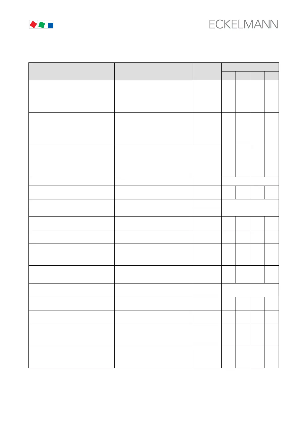
S Menu 3-1 System Configuration (CL1)
CONFIG POS: XXXXX Entry
Default
NT LT HP Dim.
No. Comp./Cond CL1 XX Number of compressors/fans (base load
stages) in CL1
With step control:
With speed control:
With combined control:
0 - max.
1)
1 or 2
min. 2-max.
1
)
2/4/6
1)
2/4/6
1)
2/4/6
1)
-
Cap.Stages CL1 XX Number of capacity stages each capacity-
controlled base load stage CL1
With step control:
With speed control:
With combined control:
1 - 3
1)
= 1
= 1
1 1 1 -
No.multist. CL1 XX Number of capacity-controlled base load
stages CL1
With step control:
With speed control:
With combined control:
0 - max.
1)
= 0
= 0
0 0 0 -
Enable CL1-stages → Enable/disable control stages in CL1 → see Screen 3-1-a
Stg.Ld.Shed. CL1 X Number of disabled relay/control stages
on load shedding CL1
0..3 0 0 0 -
Refrig. CL1 XXXXX → Select refrigerant in Control Loop 1 → see Screen 3-1-b
TRANSD.CL1 → Sensor matching Control Loop 1 → see Screen 3-1-c
Enab. tr CL1 Activate room/outside temperature analy
sis CL1 (only available with CAN Bus)
↑, ↓,
(ON/OFF)
OFF OFF OFF -
Enab.Humid.CL1 Activate analysis of air humidity ↑, ↓,
(ON/OFF)
OFF OFF OFF -
Node-Nr Env.CL1 CAN Bus node number of the VS
3000/VS 3000 BS from which CL1 draws
ambient data (humidity, outside/room
temperature)
1..9 - - - -
to-MinMon CL1 Activation of compressor shutdown by
shortfall relative to min. temperature CL1
(only LP control)
2)
↑, ↓,
(ON/OFF)
ON ON - -
Conumer.cont.CL1 → Select control by refrigeration point or
suction pressure Control Loop 1
2)
→ see Screen 3-1-d
Cons.nodeNo.CL1 Enter refrigeration point to control 1st con
trol loop of pack
1..99 or --- -- -- -- -
forced ret. CL1 X Select forced shutdown/oil equalization
function Control Loop 1
2)
↑, ↓, (N/Y) N N - -
Max. Off Time XXXm Enter maximum allowed run time before
forced shutdown
2)
.
Only shown when forced shutdown func
tion activated.
60..180 180 180 - min
Off Time XXXm Enter standstill time after forced shut
down
2)
.
Only shown when forced shutdown func
tion activated.
1..5 2 2 - min
1)
0 to 4/8/12 depending on expansion stage and configuration
(see section 3 Function - System Configuration/Allocation of Relay/Control Stages).
2)
CL1 must not be HP controller.