Pin and Terminal Assignments of VS 300
76
Doku-Version 2.05 - Firmware 2.10 - 15. September 2017
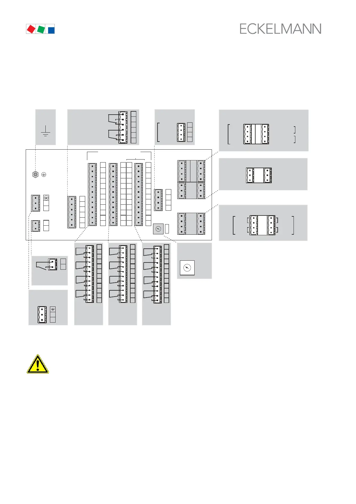
6.1 View of connecting terminals
As described in section 1 System Configuration, the VS 300 Pack Controller is of modular design. The following
view of pin and terminal assignments describes the VS 300 with all expansion stages and add-on modules fit
ted.
Rear of VS 300: Position of connecting terminals (all expansion stages and add-on modules fitted)
TTY ANALOG OUT
ALARM RELAY
230 V AC
28
26
25
18
16
15
RELAY OUTPUTS 230 V AC
TEMP. INPUTS
NTC / PT1000
96
95
88
86
85
78
76
75
108
106
105
98
Z42
Z41
Z32
Z31
Z22
Z21
Z12
Z11
Z62
Z61
Z52
Z51
136
135
128
126
125
118
116
115
148
146
145
138
56
55
48
46
45
35
38
36
68
66
65
58
ZNR. 51203 50
630 E3
BASIC
CONFIGURATION
FIRST
EXPANSION
STAGE (optionally)
SECOND
EXPANSION
STAGE (optionally)
ALARM RELAY
MODULE
(
(OPTIONALLY)
ALARM ACTIV: 15,16)
TTY INTERFACE ANS ANALOG OUTPUTS
CAN BUS MODULE
(OPTIONALLY)
CAN BUS ADRESS
SELECTOR
SWITCH
RELAY/CONTROL
S1..S4
RELAY/CONTROL
S5..S8
RELAY/
CONTROL S9..S12
ADDRESS
CAN-BUS
DIGITAL 230 V AC
1
4
2
3
1
A41
A42
A51
A52
1
2
3
4
D31
D32
D41
D42
D12
D11
D21
D22
A12
A22
A32
A21
A11
A31
5
0
2
3
1
4
6
7
8
9
TTY
ANALOG
IN |
ANALOG
OUT
SUPPLY
230 V AC
L
N
14
13
FRONT PANEL
SWITCH
POWER SUPPLY
230 V AC
PE
(M4)
D31
D32
D41
D42
D12
D11
D21
D22
A
12
A22
A32
A21
A11
A31
Din 1
Din 2
Din 3
Din 4
230V
AC
230V
AC
Ain 1 +
Ain 1 4-20mA
Ain 3 +
Ain 3 4-20mA
Ain 2 +
Ain 2 4-20mA
DIGITAL INPUTS
ANALOG INPUTS
28
26
25
18
16
15
Prio 1
Prio 2
A41
A42
A51
A52
1
2
3
4
Aout 1 +
Aout 1 GND
Aout 2 +
Aout 2 GND
0-10V
RxD
GND
TxD
GND
TTY
Schirm
GND
CAN-L
CAN-H
0-10V
4
2
3
1
5
0
2
3
1
4
6
7
8
9
136
135
128
126
125
118
116
115
148
146
145
138
S9
S10
S11
S12
96
95
88
86
85
78
76
75
108
106
105
98
S5
S6
S7
S8
56
55
48
46
45
35
38
36
68
66
65
58
S1
S2
S3
S4
14
13
L
N
SWITCH
Attention is required to the following items when installing and connecting wiring:
All connecting leads from and to the VS 300 - except digital inputs and relay outputs - must be
screened in order to rule out faulty measurements and other malfunctions.
Correct polarity must be ensured on inputs and outputs with a current or voltage interface (0-10 V or
4-20 mA). Short circuiting or incorrect signal or power input can result in impairment of function or
even in destruction of VS 300 components. Always disconnect the system from power before mak
ing or separating connections on the VS 300.