Parameter List and Menu Structure of VS 300
100
Doku-Version 2.05 - Firmware 2.10 - 15. September 2017
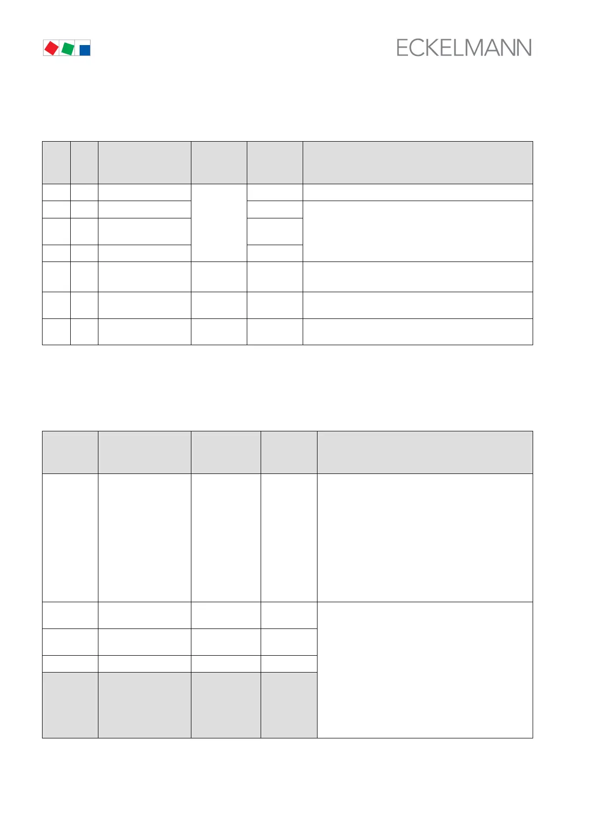
8.1.1 Parameter List A: Actual Values System Data
CL1 CL2 Function/
Description
Range Dim. Displayed / Condition
(1): Minimum of one stage must be defined in CL:
CL1: S301 > 0 / CL2: S331 > 0
A000 A010 Actual value / Pressure
1)
bar Always shown
A001 A011 Setpoint / Pressure bar
(1)
A002 A012
Actual value /
Temperature
°C
A003 A013 Setpoint / Temperature °C
A004 A014 Controller output
Analog output
0..100 % (1), an CL not step-by-step switch:
CL1: S300 > 0 / CL2: S330 > 0
A005 A015 Temperature setpoint
for setpoint shift
1)
°C (1), and temperature shift must be activated in CL1: S310 = 1 /
CL2: S340 = 1
A06 A016 Actual value Hunidity
1)
% (1), and humidity shift must be activated in CL1: S311 = 1 /
CL2: S341 = 1
1)
Range depends on controller configuration (see Parameter List S3) and operating mode!
8.1.2 Parameter List A: Common Actual Values System Data
CL 1 / CL 2 Function/
Description
Range Dim. Displayed / Condition
(1): Minimum of one stage must be defined in CL:
CL1: S301 > 0 / CL2: S331 > 0
A020.[1]
..
A020.[m]
and
A020.[n]
..
A020.[o]
Operating hours of relay
stages 1 - 12
2)
0..29999
3)
h CL1: S301 > 0
[m]=
Basic configuration (<=4): [Value S301]
1st expansion (<=8): [Value S301]
2nd expansion (<=12): [Value S301]
CL2: S331 > 0
[n]= [Value S301] + 1
[o]=
Basic configuration (<=4): [n] + [Value S331]
1st expansion (<=8): [n] + [Value S331]
2nd expansion (<=12): [n] + [Value S331]
A030 Status digital input
I1 - I4
4)
0 / 1 = Actuated -
Always shown
A035 Status Alarm output
A1 and A2
5)
0 / 1 = Actuated -
A051 Version no. [x.y] 1.3x -
A060 Enter password
Change access level
0: Setp. adjust.
not enabled
1: Setp. adjust-
ment enabled
10: Superuser
mode
-
2)
Number of relay stages CL1 [Value S301] + Number of relays CL2 [Value S331] + number internal alarm
relay <= Number of relay stages VS 300 (varying with expansion stage/number of relay stages can be 4/8/12)