Parameter List and Menu Structure of VS 300
107
Doku-Version 2.05 - Firmware 2.10 - 15. September 2017
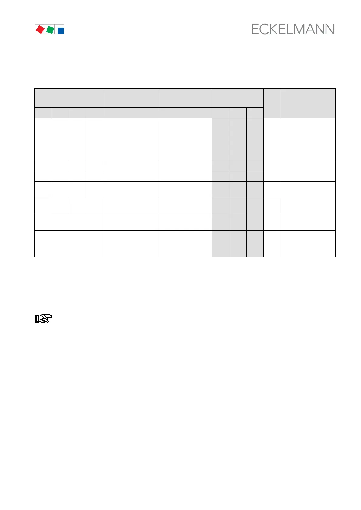
8.1.9 Parameter List S3: Common Setpoints System Configuration
Parameter No.
Function /
Description
Range Default
Dim. Displayed /
Condition
I1 I2 I3 I4 NT LT HP
S360 S364 S368 S372 Function of digital input
1 - 4
0: Off
1: Fast unload
2: Load shedding
3: Setpoint toggle
4: Alarm recording
5: HR mode
6: Safety loop
4 4 4 - Always shown
S361 S365
Allocation of digital in
put 1 - 4
0: CL1
1: CL2
2: Both control loops
0 0 0
- (1)
S369 S373
1 1 1
S362 S366 S370 S374 Polarity of digital input
1 - 4
0: Low active
1: High active
0 0 0 -
Always shown
S363 S367 S371 S375 Alarm delay for digital
input 1 - 4
0 - 60
0 0 0 s
S376 Number internal alarm
relay
0..2 *
0 0 0 -
S377 Booster operation:
Shutdown disable CL2
when compressor in
CL
0: NOT disabled
1: Disabled
0 0 - -
(1) and neither CL1 or
CL2 are permitted to
be HP controllers
I1 to I4: Digital inputs 1 - 4
(1): Minimum of one stage must be defined in CL:
CL1: S301 > 0
CL2: S331 > 0
Parameter List S3: To change values set access level to setpoint adjustment enabled
(Parameter A060=1, see section 7.7 Changing the Access Level).
* Maximum value, depends on VS 300 system / number of alarm ralais: 4/8/12!