Pin and Terminal Assignments of VS 300
77
Doku-Version 2.05 - Firmware 2.10 - 15. September 2017
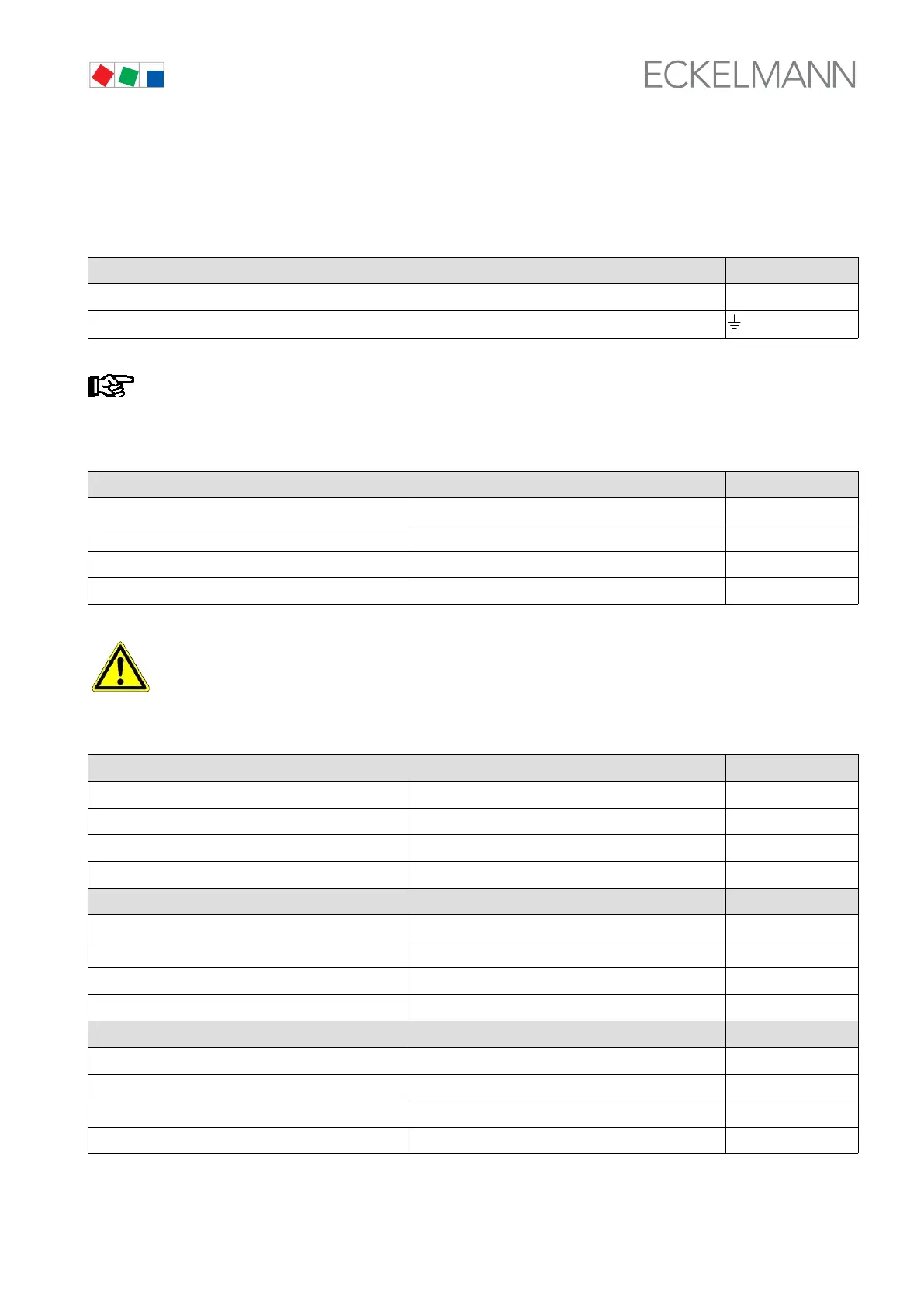
6.2 Pin assignments and their function
Power supply
Basic configuration - Function Terminal No.
230 V AC N, L
Ground conductor
A PE screw connector (M4 thread) is provided on the rear panel for grounding and shielding use.
Digital inputs
Basic configuration - Function Terminal No.
Digital Input 1 230 V AC, floating D11, D12
Digital Input 2 230 V AC, floating D21, D22
Digital Input 3 230 V AC, floating D31, D32
Digital Input 4 230 V AC, floating D41, D42
When a digital input Fast unload extern OFF is used for a safety-critical application,
additional measures for the purpose of monitoring must be undertaken.
Relay outputs (all changeover contacts 230 V AC)
Basic configuration - Function Terminal No.
S1 - Relay/control stage 1 Stage loaded: 35, 38 35, 36, 38
S2 - Relay/control stage 2 Stage loaded: 45, 48 45, 46, 48
S3 - Relay/control stage 3 Stage loaded: 55, 58 55, 56, 58
S4 - Relay/control stage 4 Stage loaded: 65, 68 65, 66, 68
1st expansion stage - Function
S5 - Relay/control stage 5* Stage loaded: 75, 78 75, 76, 78
S6 - Relay/control stage 6* Stage loaded: 85, 88 85, 86, 88
S7 - Relay/control stage 7* Stage loaded: 95, 98 95, 96, 98
S8 - Relay/control stage 8* Stage loaded: 105, 108 105, 106, 108
2nd expansion stage - Function
S9 - Relay/control stage 9** Stage loaded: 115, 118 115, 116, 118
S10 - Relay/control stage 10** Stage loaded: 125, 128 125, 126, 128
S11 - Relay/control stage 11** Stage loaded: 135, 138 135, 136, 138
S12 - Relay/control stage 12** Stage loaded: 145, 148 145, 146, 148
* From 1st expansion stage
** From 2nd expansion stage