Parameter List and Menu Structure of VS 300
117
Doku-Version 2.05 - Firmware 2.10 - 15. September 2017
8.4 Menu structure
Main Menu overview
Depending on type, expansion stage and configuration of the system, alternative terms may be used in menus
and screens. These terms are shown in italics in the menus and screens that follow.
Example: Compressor / Fan CL2
S The display of the operator terminal will show either Compressor or Fan depending on whether the control
loop is configured for high or low pressure!
S CL2 stands for either NT2 - normal-temperature refrigeration, LT2 - low-temperature refrigeration or HP2 -
high pressure in Control Loop 2.
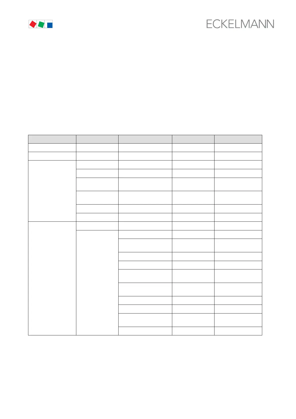
Level 1 Level 2 Level 3 Screen No. Screen Name
Main menu 0 VS 300
Overview Show actual values 1 --
Actual values
2 ACT.VALUES
Analog values Show actual values 2-1 ANALOGV.
Compressor / Fan
CL1
Show relay stage status
CL1
2-2 CL 1 COMP /
COND
Compressor / Fan
CL2
Show relay stage status
CL2
2-3 CL 2 COMP /
COND
Internal Alarm Show internal alarm relay 2-4 Int. Alarm
System Show input/output status 2-5 SYSTEM
Setpoints
3 SETPOINTS
System configuration
3-1 CONFIG
Enable/disable control sta
ges CL1
3-1-a CL 1 COMP /
COND
Refrigerant CL1 3-1-b REFRIGT
Sensor matching CL1 3-1-c TRANSD.CL1
Select refrigeration point/
suction pressure CL1
3-1-d CONT TYPE
Enable/disable control sta
ges CL2
3-1-e CL2-COND/FAN
Refrigerant CL2 3-1-f REFRIGT
Sensor matching CL2 3-1-g TRANSD.CL2
Select refrigeration point/
suction pressure CL2
3-1-h CONT TYPE
Controller configuration 3-1-i Config