Operation of VS 300
80
Doku-Version 2.05 - Firmware 2.10 - 15. September 2017
(4/5/6/7) Green trend LEDs for Control Loop 1 (4/5) and for Control Loop 2 (6/7):
Y Upper LED: (5) or (6) Temperature/pressure high, above neutral zone
Both LEDs: (4/5) or (6/7) Temperature/pressure within neutral zone
B Lower LED: (4) or (7) Temperature/pressure low, below neutral zone
Status display by simultaneously pressing the ↑ and ↓ keys:
(8/9) Load shedding: Status display by LED segment below symbol (8) for Control Loop 1 /
below symbol (9) for Control Loop 2
(10/11) 2nd setpoint active: Status display by LED segment below symbol (10) for Control Loop 1 /
below symbol (11) for Control Loop 2
(12/13) Heat recovery mode: Status display by LED segment above symbol (12) for Control Loop 1 /
above symbol (13) for Control Loop 2
(14/15) Fast unload: Status display by LED segment above symbol (14) for Control Loop 1 /
above symbol (15) for Control Loop 2
Other indicating functions
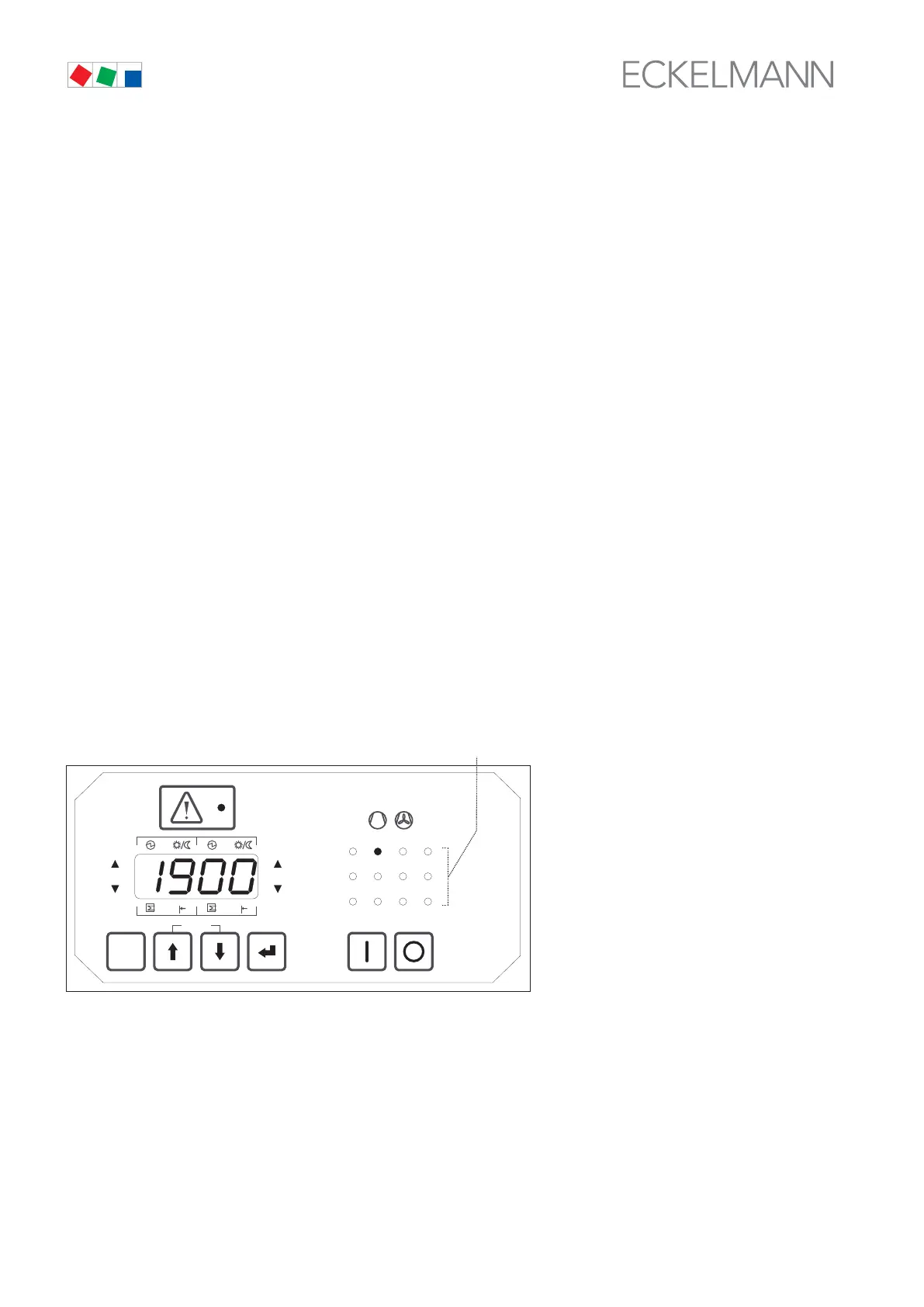
The relay/control stage operating and status display (3) is used for indicating figures exceeding four digits (e.g.
21,900 operating hours) by one of these LEDs flashing, as shown below.
Value = Value of LED display [0 - 9999] + (Number of flashing operating and status display LED * 10000)
Example: Figure shown on four-digit display: 1900 h
Number of flashing operating and status display LED: 2
Result: 1900 + (2 * 10000) = 21900 operating hours
ESC
RESET
1 2 3 4
1 2
5 6 8
9 10 11 12
7
Status
12
OFF
ZNR. 51203 52
630
OFF
(3)