Parameter List and Menu Structure of VS 300
104
Doku-Version 2.05 - Firmware 2.10 - 15. September 2017
CL1 CL2 Function/
Description
Range Default Dim.
Displayed / Condition
(1): Minimum of one stage must be defined in
CL:
CL1: S301 > 0
CL2: S331 > 0
(2): Only shown when CL configured as HP
controller
NT LT HP
S234 S274 Minimum FC speed with
continuous control
0..50 0 0 0 %
(1) and speed controller must be active in respective
CL:
CL1: S300 > 0
CL2: S330 > 0
S235 S275 Regulating speed for
analog controller output
with continuous control
-15..15 0 0 0 -
S236 S276 Maximum temperature
with speed control
-35..45 -8 -25 40 °C
S277 No. of compressors run
ning in CLK1 at HP fault
in CL2
0..
1) - - 1) -
(1) and CL1 configured as LP controller
(NT or LT) and CL2 as HD controller.
S238 Minimum allowed diffe
rence between to and tc
5..15 / --- --- --- - K
Parameter List S1 and S2: To change values set access level to setpoint adjustment enabled
(Parameter A060=1, see section 7.7 Changing the Access Level).
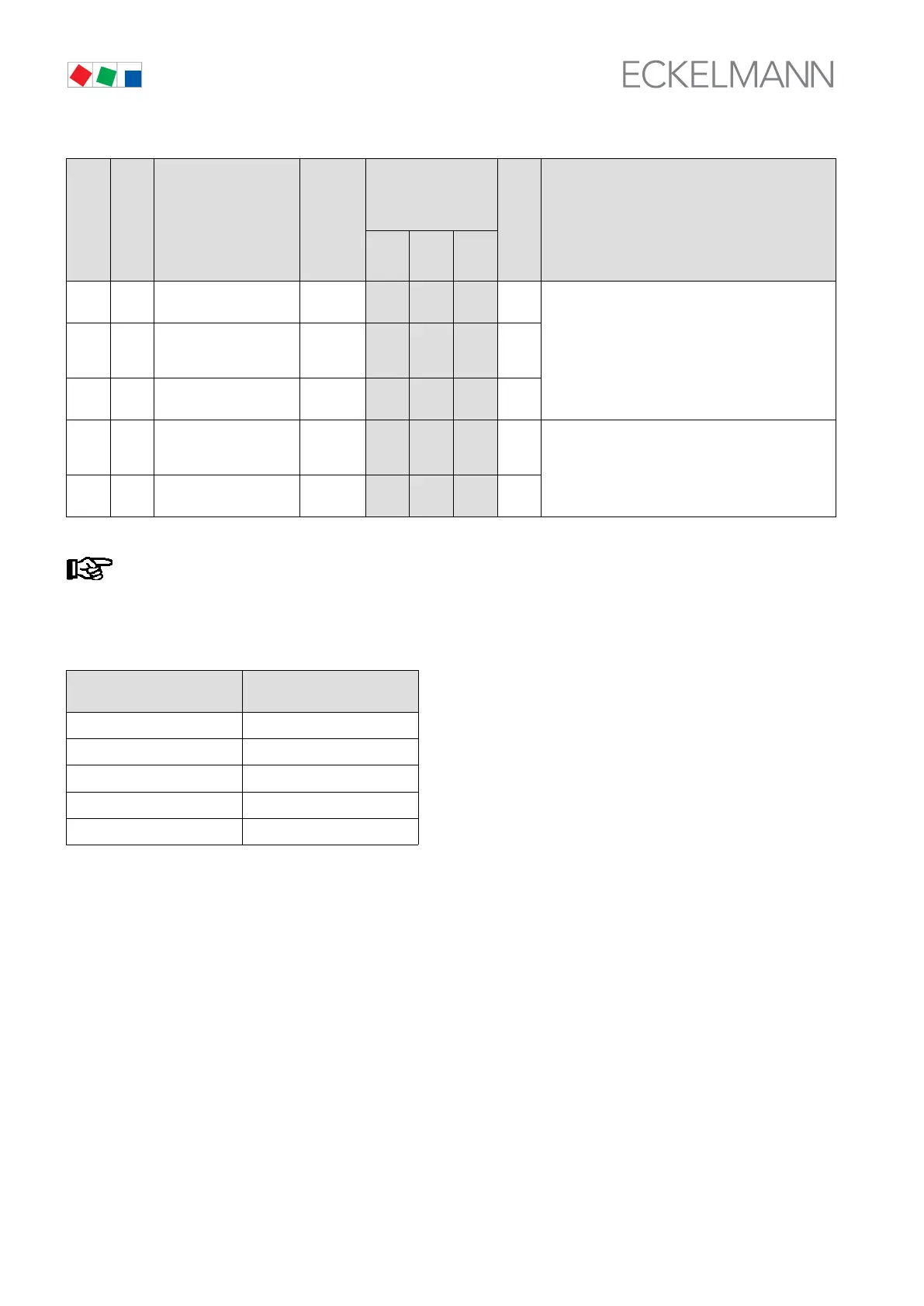
1)
After changing compressor stages in CL1, this value is reset to the new default according to the table below:
No. of compressor stages Default No. of compressor
stages at HP fault
1 - 2 1
3 - 5 2
6 - 7 3
8 - 10 4
11 - 12 5