System Design of VS 300
8
Doku-Version 2.05 - Firmware 2.10 - 15. September 2017
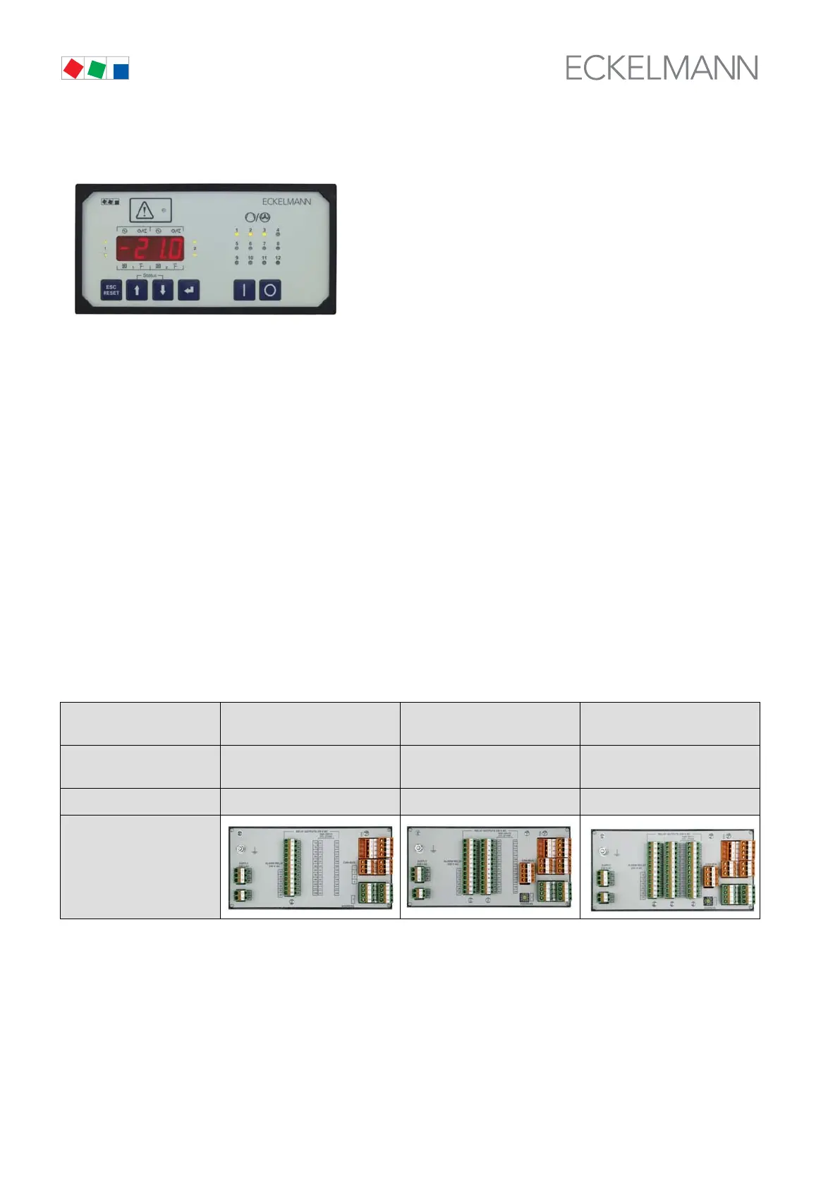
Basic configuration - Front
1x Front operator panel with 4-digit 7-segment LED display
12 x Status LEDs indicating operating status of the relay/control stages
4 x Trend LEDs showing temperature/pressure status
(high, low or within neutral zone)
4 x Operating keys and a universal switching contact.
Basic configuration - Rear
1 x Analog/digital IO module
S 4 digital inputs 230 V AC
S 2 analog inputs, pressure transducer 4-20 mA
S 2 analog outputs, speed adjuster/FC 0-10 V
S TTY port
1 x Universal contact to actuate external devices
1 x Power supply connection
Available expansion stages:
Number of
relay modules
1
(with 4 relay outputs)
2
(with 8 relay outputs)
3
(with 12 relay outputs)
CAN bus without CAN bus module
(stand alone operation)
with CAN bus module* with CAN bus module*
Order number
EVS300A001 EVS300A003 EVS300A004
* CAN bus module
With the CAN bus module added, the VS 300 Pack Controller can be operated fully by a connected terminal
(AL 300 Alarm Terminal or CI 3000 Store Computer), messages/alarms can be retrieved and processed, or the
controller can be integrated in the LDSWin remote monitoring system.