Function of VS 300
41
Doku-Version 2.05 - Firmware 2.10 - 15. September 2017
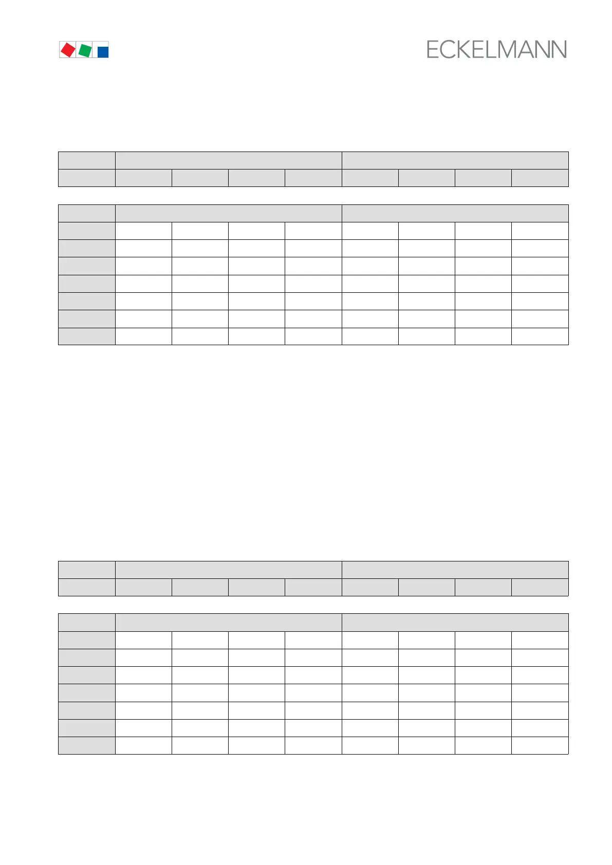
Control Loop 1 – Compressor loading:
The following table is an example of the compressor loading sequence:
VS 300 Basic configuration First expansion stage
Relay No. S1 S2 S3 S4 S5 S6 S7 S8
Control loop Control Loop 1 (CL1) Control Loop 2 (CL2)
Action GS1
CL1
LS2
CL1
LS3
CL1
GS4
CL1
GS1 GS2 GS3 -
1 X
2 X X
3 X X X
4 X X
5 X X X
6 X X X X
GS1
CL1
= Base load Compressor 1 (capacity-controlled)
LS2 - LS3 = Capacity Stage 2 – 3 associate to GS1
GS4
CL1
= Base load stage Compressor 2 (no capacity control)
Unloading takes placed by first shutting down the capacity stages of a capacity-controlled compressor. Com
pressors without capacity control are subsequently unloaded successively when the capacity-controlled unit is
running at minimum capacity.
When unloading, the compressors without capacity control are unloaded first. So as to achieve finer graduation,
the capacity stages of a capacity-controlled compressor are loaded for it to run at 100% when a non-capacity-
controlled compressor is unloaded. These capacity stages are successively unloaded if refrigeration demand
continues low.
The following table is an example of the compressor unloading sequence:
Control Loop 1 – Compressor unloading:
VS 300 Basic configuration First expansion stage
Relay No. S1 S2 S3 S4 S5 S6 S7 S8
Control loop Control Loop 1 (CL1) Control Loop 2 (CL2)
Action GS1 LS2 LS3 GS4 GS1 GS2 GS3 -
1 X X X X
2 X X X
3 X X
4 X X X
5 X X
6 X