Titanium Interfaces User Guide
SEU Detection Circuitry
Your user logic connects to the SEU detection circuitry using the following pins.
Table 4: SEU Detection Pins
GUI Option Default Signal Name Direction Description
SEU Start Detection Pin
Name
seu_START Input Manual mode only. To use this pin to initiate an
SEU check, pulse this signal high for a minimum
pulse of 500 ns.
Error Injection Pin
Name
seu_INJECT_ERROR Input This signal forces an SEU error so you can test
the how the SEU detection circuitry interacts
with your user design during testing and
development. To inject an error, pulse this signal
high for a minimum pulse of 500 ns.
Pull this signal low when you are not using it.
Error Reset Pin Name seu_RST Input This pin sets the Error Status pin to low to clear
the error and restart SEU detection monitoring.
To reset SEU monitoring, pulse this signal high
for a minimum pulse of 500 ns.
Error Status Pin Name seu_ERROR Output If the FPGA detects an SEU, this signal goes high.
It does not go low until you toggle the Error
Reset pin.
Reconfiguration Pin
Name
seu_CONFIG Input If the FPGA is using active configuration mode,
you can use this pin to trigger the FPGA to
reconfigure; the FPGA does not automatically
reconfigure when an error is detected. Pulse this
signal high for a minimum pulse width of 500 ns.
If you are using passive configuration mode
or JTAG configuration, you cannot trigger
reconfiguration with this signal.
SEU Done Detection
Pin Name
seu_DONE Output This signal goes high when the SEU detection
circuitry has completed calculating the CRC
and comparing it to the stored one. If an SEU
occurred, this signal stays high until you reset the
circuitry.
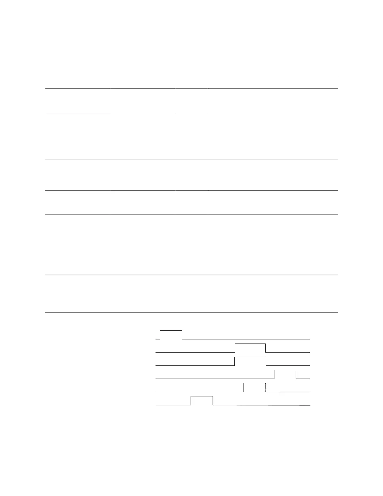
Figure 7: SEU Signal Waveform
www.efinixinc.com 19