Titanium Interfaces User Guide
Create a TX Serializer Interface
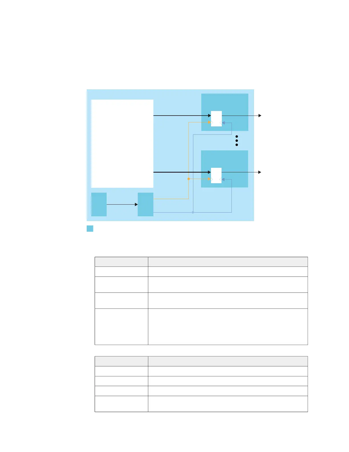
The following figure shows a completed TX serializer interface, the serialization width is
always 4 and m is the number of TX lanes.
Figure 20: Complete TX Serializer Interface Block Diagram
PLL
OUTCLK
OUTFASTCLK
Serializer
OUT[3:0]
Serializer
OUT[3:0]
GPIO TXm
GPIO
PLL_CLKIN
m is the number
Follow these steps to build this interface using the Efinity
®
Interface Designer.
1. Add a PLL block with the following settings:
Option Description
Resource You can use any PLL resource.
Reference
Clock Mode
Any
Reference Clock
Frequency
Any
Output Clock Define the output clocks so that you have one for the fast clock
(serial) and one for the slow clock (parallel).
The fast clock (OUTFASTCLK) should be 4 times faster than the
slow clock (OUTCLK). The serial clock phase shift should be
between 45 and 135 degrees.
2. Add a GPIO block with these settings to provide the reference clock input to the PLL:
Option Description
Mode Input
Pin Name Any
Connection Type pll_clkin
GPIO Resource Assign the dedicated PLL_CLKIN pin that corresponds to the PLL
you chose.
3. Add a GPIO block with these settings:
www.efinixinc.com 54