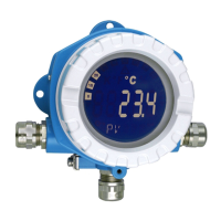
Technische Daten iTEMP TMT162
48 Endress+Hauser
Load
R
b max.
= (U
b max.
- 11.5 V) / 0.023 A
(current
output)
Ub
42 V
1348
1098
250
11.5 V
0
36.25 V
17.25 V
Supply voltage (V DC)
Load (Ω)
A0033806-EN
Linearization/transmission
behavior
Temperature-linear, resistance-linear, voltage-linear
Mains filter 50/60 Hz
Filter 1st order digital filter: 0 to 120 s
Protocol-specific data
Manufacturer ID 17 (0x11)
Device type ID 0x11CE
HART
®
specification 7.6
Device address in the
multi-drop mode
1)
Software setting addresses0 to 63
Device description
files (DTM, DD)
Information and files can be found:
www.endress.com
www.fieldcommgroup.org
HART load min. 250 Ω
HART device variables The measured values can be freely assigned to the device variables.
Measured values for PV, SV, TV and QV (first, second, third and fourth device variable)
• Sensor 1 (measured value)
• Sensor 2 (measured value)
•
Device temperature
• Average of the two measured values: 0.5 x (SV1+SV2)
• Difference between sensor 1 and sensor 2: SV1-SV2
• Sensor 1 (backup sensor 2): If sensor 1 fails, the value of sensor 2 automatically
becomes the primary HART
®
value (PV): sensor 1 (OR sensor 2)
• Sensor switching: If the value exceeds the configured threshold value T for sensor 1,
the measured value of sensor 2 becomes the primary HART
®
value (PV). The system
switches back to sensor 1 if the measured value of sensor 1 is at least 2 K below T:
sensor 1 (sensor 2, if sensor 1 > T)
• Average: 0.5 x (SV1+SV2) with backup (measured value of sensor 1 or sensor 2 in
the event of a sensor error in the other sensor)
Supported functions • Burst mode
1)
• Squawk
• Condensed status
1) Not possible in the SIL mode, see Functional Safety Manual SD01632T/09
Wireless HART data
Minimum starting voltage 11.5 V
DC
Start current 3.58 mA
Starting time • Normal operation: 6 s
• SIL mode: 29
s

 Loading...


