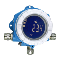
iTEMP TMT162 Technische Daten
Endress+Hauser 49
Minimum operating voltage 11.5 V
AC
Multidrop current 4.0 mA
1)
Time for connection setup • Normal mode: 9 s
• SIL mode: 10 s
1) No Multidrop current in SIL mode
Write protection for device
parameters
• Hardware: Write protection using DIP switch on electronics module in the device
• Software: Write protection using password
Switch-on delay • Until the start of HART
®
communication, approx. 10 s, during switch-on delay = I
a
≤ 3.6 mA
• Until the first valid measured value signal is present at the current output, approx. 28 s,
during switch-on delay = I
a
≤ 3.6 mA
13.3 Power supply
Supply voltage
Values for non-hazardous areas, protected against polarity reversal:
•
11.5 V ≤ Vcc ≤
42 V (standard)
• I ≤ 23 mA
Values for hazardous areas, see Ex documentation → 61
The transmitter must be powered by an 11.5 to 42 V
DC
power supply in accordance
with NEC Class 02 (low voltage/low current) with restricted power limited to 8 A
/
150 VA in the event of a short-circuit (in accordance with IEC 61010-1, CSA
1010.1-92).
Current consumption
Current consumption
Minimum current consumption
Current limit
3.6 to 23 mA
≤ 3.5 mA, Multidrop mode 4 mA (not possible in SIL mode)
≤23 mA
Terminals 2.5 mm
2
(12 AWG) plus ferrule
Cable entries
Version Type
Thread 2x thread ½" NPT
2x thread M20
2x thread G½"
Cable gland 2x coupling M20
Cable specification → 17
Residual ripple Perm. residual ripple U
SS
≤ 3 V at U
b
≥ 13.5 V, f
max.
=
1 kHz
Surge arrester The surge arrester can be ordered as an optional extra. The module protects the electronics
from damage from overvoltage. Overvoltage occurring in signal cables (e.g. 4 to 20 mA,

 Loading...


