Rev. A Disassembly, Assembly, and Adjustments 5-25
TM-U950/U950P Technical Manual
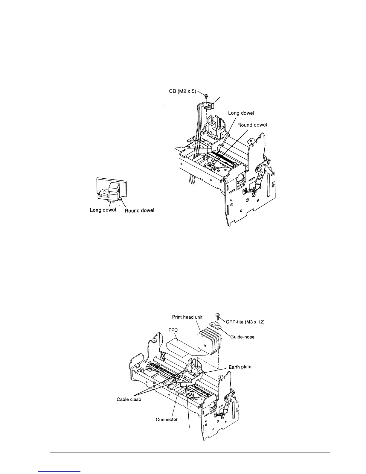
Sub-assembly L-(1)
15. Mount the detector-carriage sub-assembly so that it is flush with the round dowel and long
dowel, as shown in the illustration. Then tighten the screw.
16. Engage the FPC on the cable clasp. Mount the guide-nose onto the print head unit, and then
attach them and tighten the screw.
17. Plug the FPC into the board-head relay assembly.
✔
Checkpoint
Verify that the FPC is not deformed.
Verify that the print head unit is in contact with the ground plate.
Detector-carriage sub-assembly
Carriage-head assembly
CONFIDENTIAL
 Loading...


