1-20 Features and General Specifications Rev. A
Parity (*) None, even, odd
Number of stop bits 1 or more
Connector type D-SUB 25 female or equivalent
(*)Can be set with DIP switches on the bottom of the unit (See Tables 1-9 and 1-10.)
On-line/off-line switching
This printer has no on-line/off-line switch. It automatically goes off-line in the following cases:
❏ During self-test.
❏ When the cover is open.
❏ When the paper feed button (receipt or journal/slip) is used to advance the paper.
❏ When printing has stopped due to no paper (“no paper” condition selected with ESC c 4).
❏ During the interval between power-on (including reset using the interface) and the end of
the initialization sequence, until data can be received.
❏ When an error has occurred
❏ During the macro execution switch waiting status.
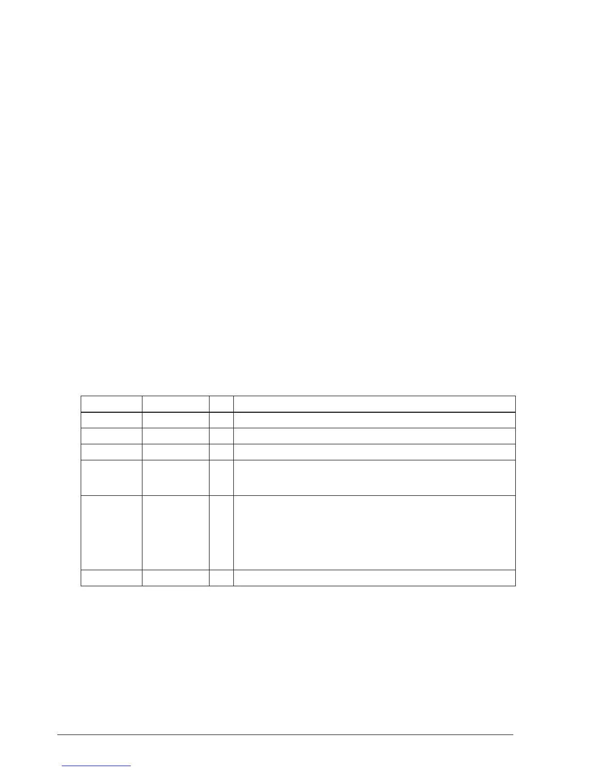
Table 1-7. Interface Connector Specifications and Functions
Pin number Signal name I/O Function
1FG—Frame ground
2 TXD O Transmit data
3 RXD I Receive data
4RTSO
DIP SW1-6 off: Same as DTR signal (Pin20)
DIP SW1-6 on: Logical product of DTR signals of DM-D and TM (if both are
SPACE, the printer can receive data.
6DSRI
Indicates whether the host is ready to receive data. SPACE indicates
“ready,” and MARK indicates “not ready.” If DTR/DSR control is used, the
printer checks this signal before sending data (except when sending
data by GS ENG, DLE ENQ, GS a). If XON/OFF control is used, this signal is
not checked.This signal can be used to reset the printer according the
DIP switch settings. The printer is reset when the signal is MARK with more
than 1 ms pulse width.
7SG—Signal ground
CONFIDENTIAL