User Manual LTU Orion 3
13
Supported management features:
• Local Craft Terminal (RS-232), Telnet, SNMP and WEB
• Two levels of system users: administrator and user, protected with passwords
Supported operating modes:
• Multi-Service Operation, Point-to-Point, Point-to-Multipoint and Ring Applications
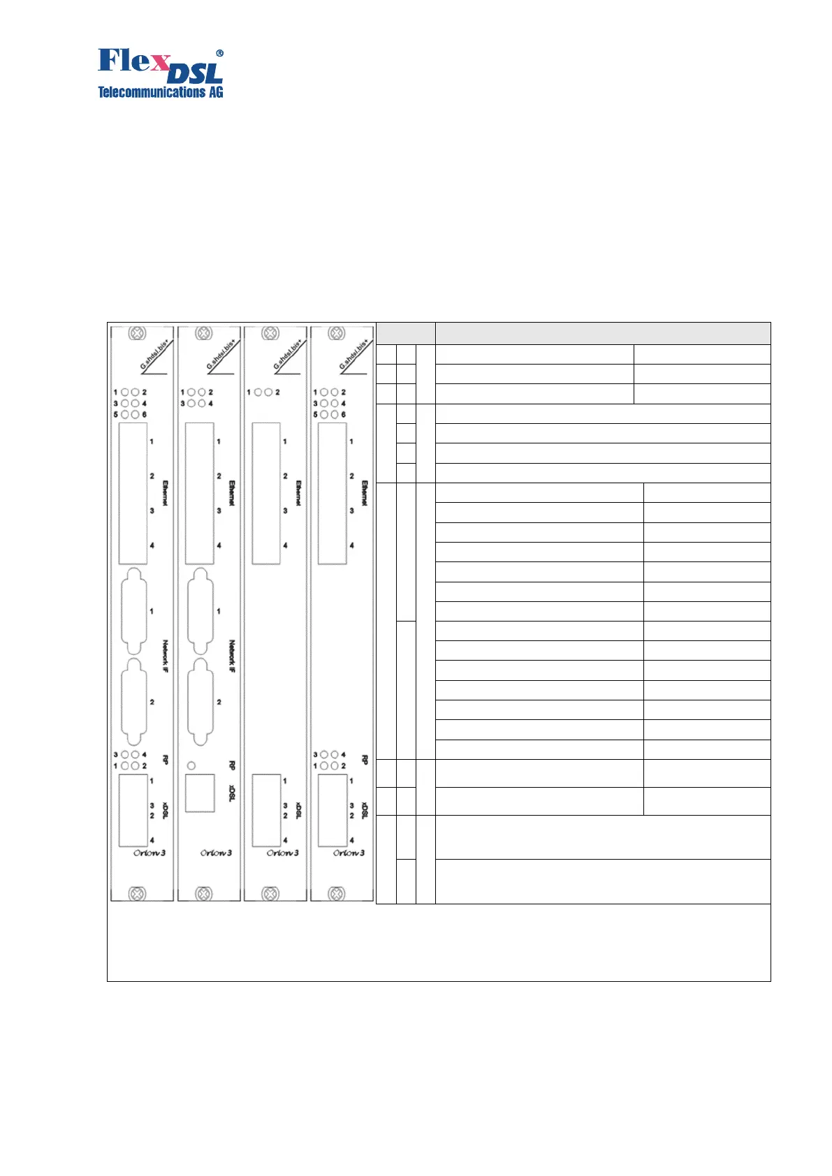
3.2 Description of Orion3 LTU Devices
Orion3 subrack devices represent a printed circuit board with a front panel. The following LEDs
and connectors are located on the front panel of the device:
LED: status remote device
LED: status 3
rd
E1 port or Nx64/RS IF
RJ45: 1
st
Ethernet Interface
RJ45: 2
nd
Ethernet Interface
RJ45: 3
rd
Ethernet Interface
RJ45: 4
th
Ethernet Interface
FG-PAM-SRL-2E1B/4Eth-RP,V90
FG-PAM-SRL-2E1B/N64/4Eth-RP,V91
FG-PAM-SR2L-4E1B/4Eth-RP,V93
FG-PAM-SR2L-2E1B/N64/4Eth-RP,V94
FG-PAM-SR4L-4E1B/4Eth-RP,V96
FG-PAM-SR4L-2N64/4Eth,V98
FG-PAM-SR4L-2N64/4Eth-RP,V98
FG-PAM-SRL-2E1B/4Eth-RP,V90
FG-PAM-SRL-2E1B/N64/4Eth-RP,V91
FG-PAM-SR2L-4E1B/4Eth-RP,V93
FG-PAM-SR2L-2E1B/N64/4Eth-RP,V94
FG-PAM-SR4L-4E1B/4Eth-RP,V96
FG-PAM-SR4L-2N64/4Eth,V98
FG-PAM-SR4L-2N64/4Eth-RP,V98
LED: Status RP (remote power) 3
rd
DSL
LED: Status RP (remote power) 1
st
DSL
RJ45 con. 1
st
and 3
rd
DSL line + two LEDs
RJ45 con. 2
nd
and 4
th
DSL line + two LEDs
A) B) C) D)
A) FG-PAM-SR2L-4E1B/4Eth-RP,V93 / FG-PAM-SR2L-2E1B/N64/4Eth-RP,V94 / FG-PAM-SR4L-4E1B/4Eth-RP,V96 / FG-PAM-
SR4L-2N64/4Eth,V98 / FG-PAM-SR4L-2N64/4Eth-RP,V98
B) FG-PAM-SRL-2E1B/4Eth-RP,V90 / FG-PAM-SRL-2E1B/N64/4Eth-RP,V91
C) FG-PAM-SR4L-4Eth,V98
D) FG-PAM-SR4L-4Eth-RP,V98
Table 3.1 Connectors and LEDs on the front panel of the LTU devices