User Manual LTU Orion 3
46
3.3 Alarm Indication
When managing the device via the local craft terminal (RS-232) or via Telnet, all LEDs, except
the Ethernet LEDs will blink with a frequency of 1 Hz.
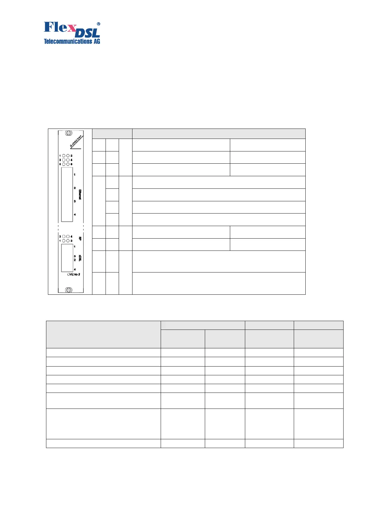
3.3.1 LEDs
The LEDs display the normal operation conditions and alarm conditions of a device.
LED: status remote device
LED: status 3
rd
E1 port or Nx64/RS IF
Status 1
st
Ethernet Interface
Status 2
nd
Ethernet Interface
Status 3
rd
Ethernet Interface
Status 4
th
Ethernet Interface
LED: Status RP (remote power) 3
rd
DSL
LED: Status RP (remote power) 1
st
DSL
Status 1
st
DSL line
Status 3
rd
DSL line
Status 2
nd
DSL line
Status 4
th
DSL line
Table 3.11 LED behaviour according the device status
Power failure or power is off
Hardware or software failure
Non-urgent alarm at E1 (Nx64)
interface
E1 (Nx64) interface data is not used
for transmission into SHDSL line
interface nor for Ethernet data
transmission
Urgent alarm at the line interface