EasyManua.ls Logo

Fluke 9500B - Page 231

Fluke 9500B
297 pages
Print Icon
To Next Page IconTo Next Page
To Previous Page IconTo Previous Page
Loading...
Section 9: Verifying the Model 9500B Accuracy Specification 9-21
Final Width = 215mm
ACTIVE HEAD
INPUT
4955
CALIBRATION ADAPTOR
W
230 Vpk
230 Vpk
Case Lo Hi
DCV o/c
DCV 50
Meas 50
SQV o/c
SQV 50
Ref 50
Ref 50k
Meas 50k
Ref 1M
Meas 1M
Ref 19M
Meas 19M
Standards DMM
I+ I-
Hi Lo
Reset
Guard


!
Guard
4955



230V PK MAX
CH 1
CH 2
CH 3
CH 4
CH 5






9500
Active Head
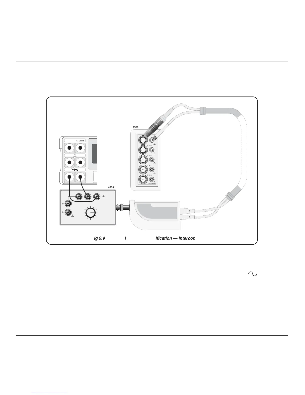
Fig 9.9.1.1 LF Sine Voltage Verification — Interconnections
9.9.1.3 Interconnections
9.9.1.4 Verification Setup
1. Connections Ensure that the 9500B is connected to the DMM as
shown in Fig. 9.9.1.1, or via a similar PC3.5 or
BNC-4mm adaptor, and that both instruments are
powered on and warmed up.
2. 9500B Ensure that the 9500B is in MANUAL mode and
then select the Sine function (
key). Select the
required output Signal Channel (50 Load).

Table of Contents