9-22 Section 9: Verifying the Model 9500B Accuracy Specification
Final Width = 215mm
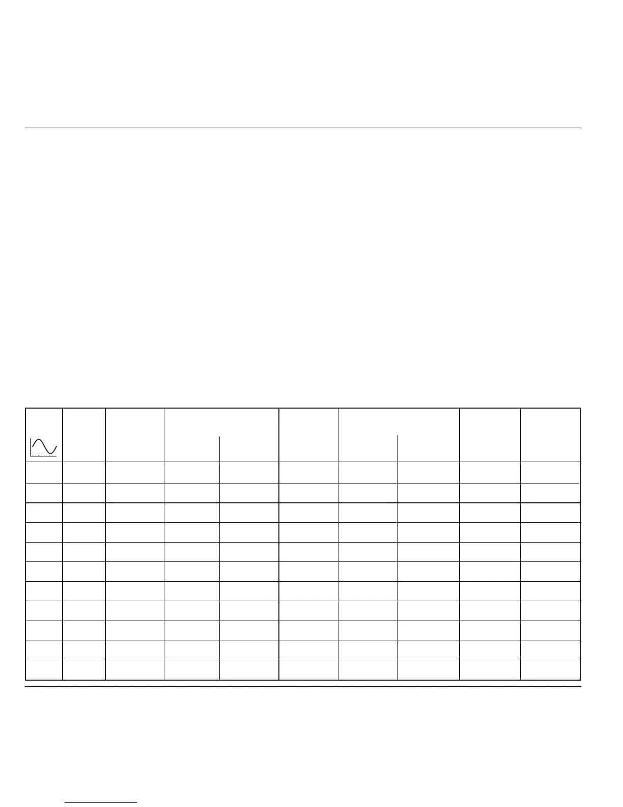
Verif. Freq. Output Tolerance Output Tolerance Measured Calculated
Point. Voltage Limits (pk-pk) Voltage Limits (RMS) Value Value
(pk-pk) Lower Higher (RMS) Lower Higher (RMS)
SGN1 1kHz 1.0000V -0.015V 0.015V 0.35355V -5.3mV 5.3mV
SGN2 1kHz 300.00mV -4.5mV 4.5mV 106.066mV -1.59mV 1.59mV
SGN3 1kHz 100.00mV -1.5mV 1.5mV 35.3553mV -0.53mV 0.53mV
SGN4 45kHz 1.0000V -0.015V 0.015V 0.35355V -5.3mV 5.3mV
SGN5 45kHz 300.00mV -4.5mV 4.5mV 106.066mV -1.59mV 1.59mV
SGN6 45kHz 100.00mV -1.5mV 1.5mV 35.3553mV -0.53mV 0.53mV
SGN7 50kHz 3.0000V 2.955V 3.045V 1.06066V 1.04475V 1.07657V NA
SGN8 50kHz 1.0000V 0.985V 1.015V 0.35355V 0.34825V 0.35885V NA
SGN9 50kHz 300.00mV 295.5mV 304.5mV 106.066mV 104.475mV 107.657mV NA
SGN10 50kHz 100.00mV 98.50mV 101.5mV 35.3553mV 34.8250mV 35.8856mV NA
SGN11 50kHz 30.000mV 29.55mV 30.45mV 10.6066mV 10.4475mV 10.7657mV NA
Table 9.9.1.1 Sine Verification into 50W Load
Please copy the following table. Enter the measurements in the Measured Value column on the copy and calculate as shown:
9.9.1.5 Verification Procedure
1. Verification Points Refer to Table 9.9.1.1.
2. DMM Select the correct RMS Voltagerange for the
verification point RMS Output Voltage.
3. 9500B Set the Output Voltsp-p as required for the
verification point:
4. 4955 If using the Model 4955 Calibration Adaptor, set its
switch to 'SQV50W '. If not using the Model 4955,
ensure that the DMM input is AC-coupled at 50W
input impedance.
5. 9500B Set Output ON and wait for the DMM reading to
settle.
N.B. For Operation (6), the RMS Output Voltage values, and RMS
Tolerance Limits have been derived using the following factor
for the output waveform:
(at 1kHz: RMS = 0.5 x 0.707107 x pk-pk)
Note: This factor applies only when the Standards DMM
input is AC-Coupled through a large capacitance.
It is based on the use of a model 4955 set to 'SQV50W '.
6. Amplitude a. Measure the RMS Output Voltage value.
b. Record this value in the Measured Value
column of the copy of the Table.
d
e
c
.
.
.
For SGN1-6 check that the Calculated Value
is at or between the
RMS Tolerance Limits.
For SGN7-11 check that the Measured Value
is at or between the RMS Tolerance Limits.
For SGN1-6 calculate and record the
Calculated Values in the copy of the table.
7. 9500B Set Output OFF.
Copy the table: 9.9.1.1. Follow the correct sequence of verification points as shown on the table, and carry out the following operations (1) to
(7) at each verification point.
SGN8-SGN1
SGN9-SGN2
SGN10-SGN3
SGN8-SGN4
SGN9-SGN5
SGN10-SGN6