Section 9: Verifying the Model 9500B Accuracy Specification 9-23
Final Width = 215mm
9.9.2.1 Summary
Equipment requirements are given at para 9.9.2.2 and test
interconnections at para 9.9.2.3. Para 9.9.2.4 shows the Verification
Setup.
The Verification Procedure is at para 9.9.2.5, A short description of
Calculating Validity Tolerances is given at para 9.9.2.6, and the final
Uncertainty Calculation and Flatness Check is at para 9.9.2.7.
The Levelled Sine Function is verified by carrying out measurements
of amplitude at frequencies beween 50kHz and 6.4GHz; in the sequences
given at para 9.9.2.5, at the verification points shown in Tables 9.9.2.1,
9.9.2.2, 9.9.2.3 and 9.9.2.4.
Note: Heads can be verified only within the bandwidth of the
mainframe. e.g. Head Model 9510 with Mainframe Variant
9500B/600 can only be verified to 600MHz.
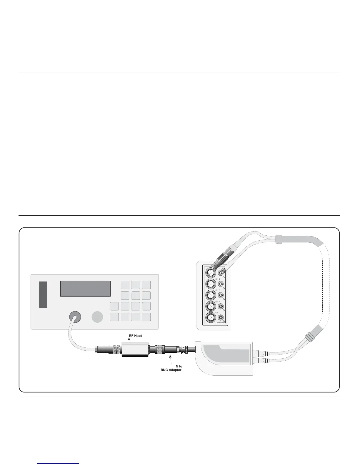
Sensor
Input
RF Power Meter
9500
Active Head
Precision-N to
BNC Adaptor
RF Head
Assembly
Fig 9.9.2.1 RF Sine Voltage Verification — Interconnections
9.9 9530/9560/9550/9510 Head Verification by Functions (Contd.)
9.9.2 Verifying the Levelled Sine Function: Flatness
9.9.2.2 Equipment Requirements
• The UUT Active Head, connected to a verified Model 9500B
Mainframe (for Mainframe verification, refer to Sub-section 9.8.3).
• RF Power Meter for Power measurements from 50kHz and 6.4GHz
and from 100mVp-p to 3Vp-p into 50Ω.
Examples: Marconi Instruments Model 6960B with Model 6912
head up to 1.1GHz or Rhode and Scwarz NRVS with NRV-Z5 head
beyond 1.1GHz.
• Precision-N to BNC Adapter for signal connection from the UUT
Active Head to the input of the RF Power Meter head for Amplitude
measurements.
Example: Huber & Suhner Adapter type no. 31BNC-N-50-51 or
31N-PC3.5-50-1.
9.9.2.3 Interconnections