Infratec™ 1241 Grain Analyzer
5:10 Service Manual 1001 5015 / Rev. 4
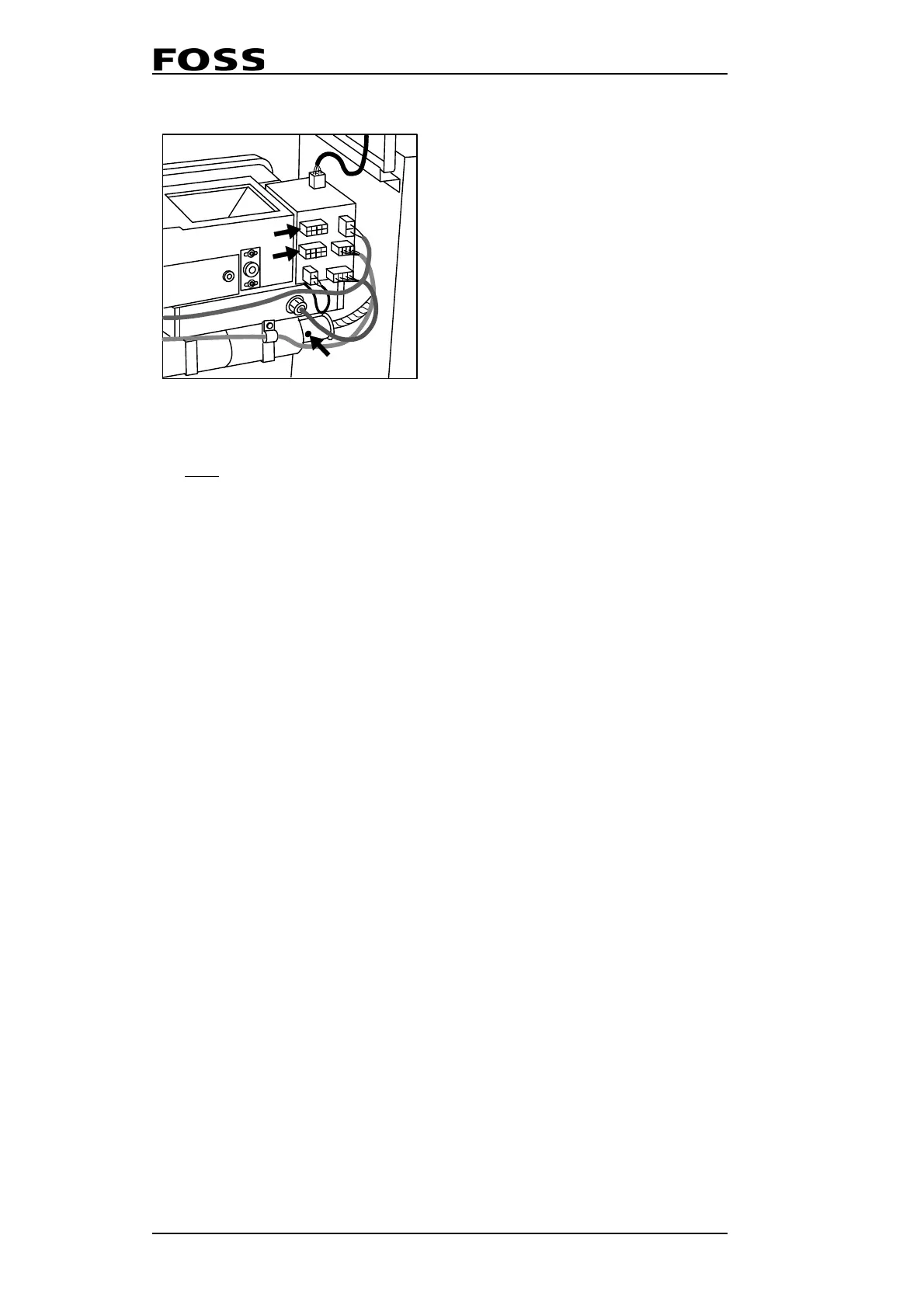
Fig. 5:11 Stop screw (pos 5)
6. Now uncovered by the protector, loosen the stop screw to the fibre optic cable
itself and remove it from the Measuring Unit. Pull from inside the compartment.
7. Remove the four screws on the backside of the instrument which fasten the
power supply module to the main chassis.
8. Pull the entire power supply module straight outwards and place the power
supply module on a table.
9. Loosen all screws and nuts to the fasteners which secure the ingoing and
outgoing fibre optic cables of the monochromator. Remove the fasteners.
10. Standing behind the instrument: Pull (but do not bend!) the outgoing fibre optic
cable (cable to MU) straight backwards and into the inside of the instrument.
NOTE! Just loosen the stop screw, do not remove. Max. one and
a half turns.
11. Remove the covers crew located in the centre of the cooling flange located on
the back side of the instrument. Place a 2 mm allen key in the exposed hole in
the flange and loosen the stop screw inside.
12. Remove ingoing fibre optic cable from cooling flange.
13. Loosen the stop screws located in the three feet of the monochromator.
14. Lift the monochromator straight upward and remove it from the instrument.
15. Place the new monochromator on the three studs in the instrument and tighten
the stop screw in each of the three feet.
16. Thread the cable fasteners on the fibre optic cables.
Mounting Fibre Optic Cable to Measuring Unit
17. Push (but do not bend!) the outgoing fibre optic cable through the through-
connection (rubber grommet) into the measuring unit compartment.
18. Being two persons will simplify this task: Slide the fibre optic cable protector
over the outgoing fibre optic cable and align the cable in the collimator. Ensure
that the fibre optic cable reach the bottom before tightening the screw. Use a
torch lamp to see the fibre optic cable come flush with the collimator. Otherwise
the screw may cause heavy scratches on the end of the fibre optic cable.
19. Tighten the stop screw.
3) Optional
4) Optional
5) Stop screw on protector
 Loading...