Infratec™ 1241 Grain Analyzer
Service Manual 1001 5015 / Rev. 4 2:19
2.2.14 Remote I/O (Optional)
Introduction
This document describes the I/O Interface and specifies the physical interfaces used
for connecting it to an Infratec 1241 or Infratec 1256. The Infratec is assumed to be
prepared for this hardware such that the back plate has got place for a High Density
DSUB15 connector for this purpose.
Connections
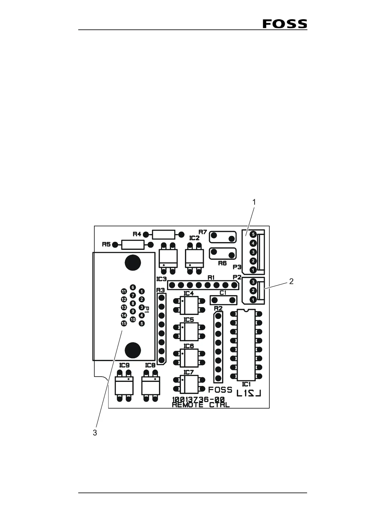
The I/O Board has three different interfaces:
• The 5-pin I2C/Power interface. The cable connecting to this interface has a 4-
way, 2-wire I²C connector that should be connected to an available I²C connector
inside the Infratec 1241/1256. The 4-way, 3-wire power connector should be
connected to an available power connector inside the Infratec 1241/1256.
• The 3-pin sensor interface could be used for connecting a "trigger"-sensor inside
the instrument.
• The 15-pin High Density DSUB15 is the interface to the outside world and is
mounted on the I/O Board and should be fastened at the back of the instrument.
Fig. 2:15 I/O Board
1 I2C/Power interface (P3) 3 DSUB15 interface (P1)
2 Sensor interface (P2)
 Loading...