Infratec™ 1241 Grain Analyzer
Service Manual 1001 5015 / Rev. 4 2:11
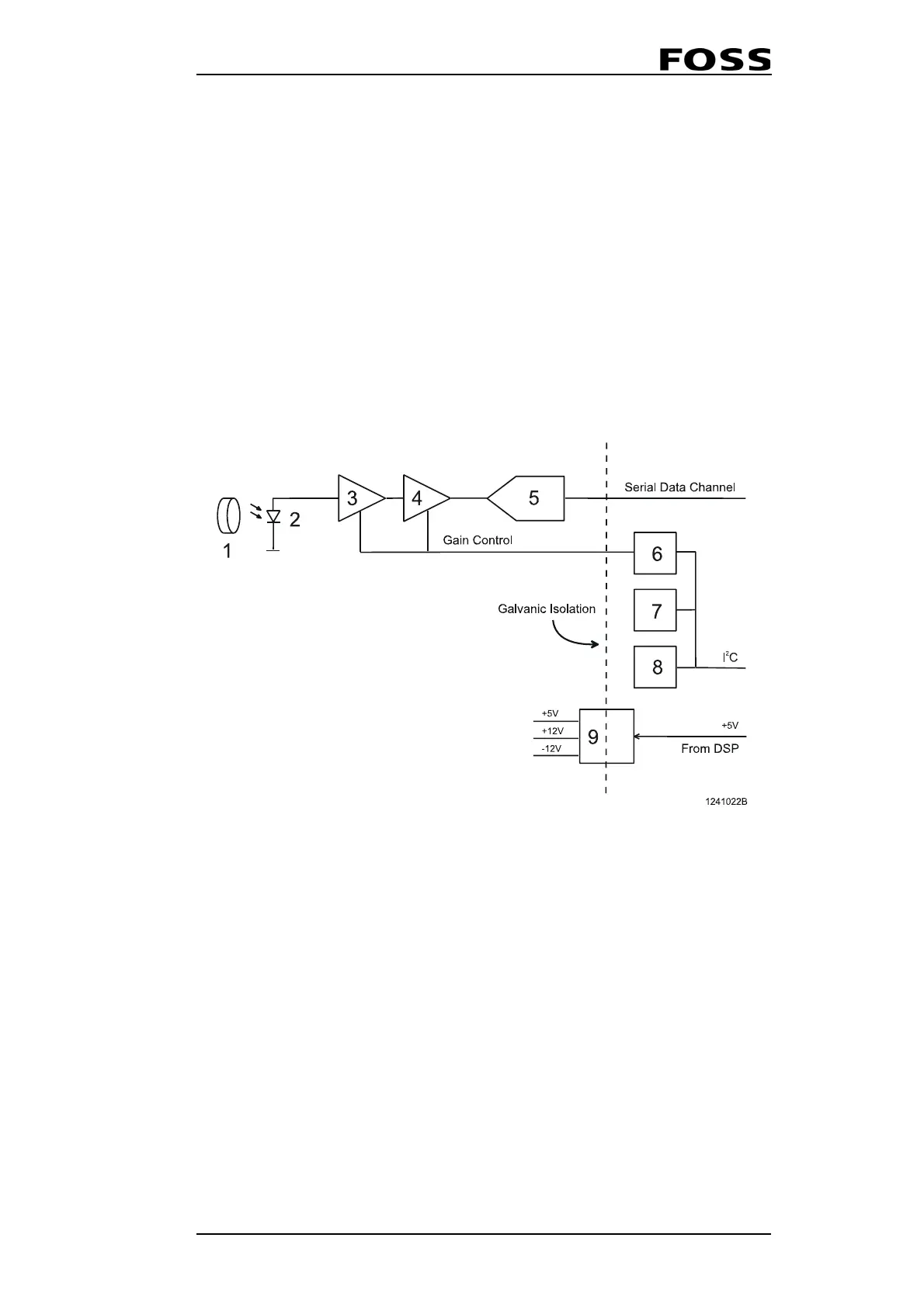
2.2.7 Detector
The detector converts light energy input to digital data output. It is constructed in a
sealed and shielded box with a window for light input and a connector for digital
input and output. The analog electronics inside the box are galvanic isolated (opto
coupled) from all I/O signals.
The detector and the DSP communicate with each other in two ways. The I
2
C bus is
used to transfer commands from the DSP to the detector, while a high speed serial
channel is used to transfer data from the detector's A/D converter.
The detector module has an I
2
C expander on board that is accessed from the DSP and
is used to set the detector gain to values specified by the ISW. It also has a
temperature sensor from which ISW reads current temperature inside the detector
and it's accessed via the I
2
C interface as well.
An E
2
PROM onboard the detector module contains the detector constants (e.g. serial
number).
Fig. 2:9 Detector Block Diagram
1 Front end optics 6 I/O expander for control signals
2 Large area silicon detector diode 7 Temperature sensor
3
Pre-amplifier stage 1 with selecta-
ble gain
8
EEPROM for calibration data stor-
age
4
Pre-amplifier stage 2 with selecta-
ble gain
9 Isolated DC/DC converter
5 16 bit 100 ksamp/sec A/D-converter
 Loading...
