Infratec™ 1241 Grain Analyzer
Service Manual 1001 5015 / Rev. 4 2:15
2.2.10 Display Interconnection Board
The Display Interconnection Board is connected between the Power Supply Board,
DSP Board and the Display. It functions as a switch whereby ISW controls LCD
Backlight and LCD Display by on/off function.
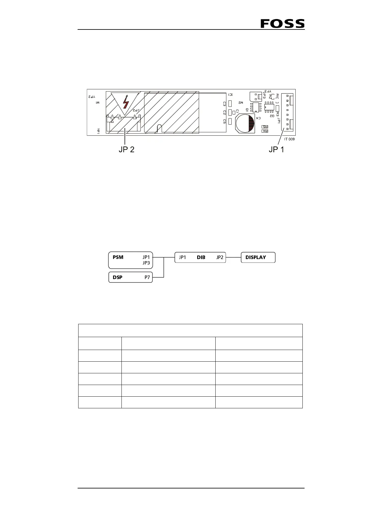
Fig. 2:12 Inverter Interface Board
The Display Interconnection Board is powered by DSP Board P7 socket.
NOTE: Backlight. Actually 600 V AC, supplied by a DC/AC
converter.
Fig. 2:13
2.2.11 Electronic ID
The Electronic ID is installed as factory standard and enables the extended
wavelength range needed for predictions in the area 570 nm - 850 nm.
The effective wavelength range of the instrument will be 570 nm-1098 nm. This
range will be activated when using an Application Model with extended range.
JP1 I2C Bus JP2 LCD Display
DIB
Connector Designation To / From
JP1/1-4 +5V, GND, +12V DSP Board (P7)
JP1/5 Not used
JP1/6-7 LCD Backlight On/Off Power Supply Board (J1)
JP1/8 LCD On/Off Power Supply Board (J3)
JP2 Output 600 VAC LCD Display
 Loading...
