Infratec™ 1241 Grain Analyzer
5:36 Service Manual 1001 5015 / Rev. 4
5.3 Measuring Unit
5.3.1 General
The following pages describes how to maintain/clean and replace parts in the
Measuring Unit module. Any kind of service that may affect the path length of the
sample kuvette is after completion subject to a perfect control and possible
adjustment of this path length.
The procedure for this adjustment is described under Preventive Maintenance
Procedures Chapter 5.7.
5.3.2 Replacement of Measuring Unit Complete
NOTE! Use ESD protection when handling circuit boards.
1. Turn off the instrument and remove the mains cable.
2. Penetrate the covers for the five holes in the left-hand door with a screwdriver.
Do not try to pinch because the door is easily miscoloured. Unscrew the screws
in the left-hand door and open it.
When re-assembling, do not forget to replace the five covers.
3. Lift the hopper and open the right-hand door.
4. Remove the Detector Cable from the DSP Board.
5. Remove Optional Equipment Power Supply Cable from the Power Supply
Module, see
Fig. 5:38 below.
6. Remove the Detector in accordance with steps 1-6 of 5.2.3 Replacement of
Detector Unit Complete on page 5:8.
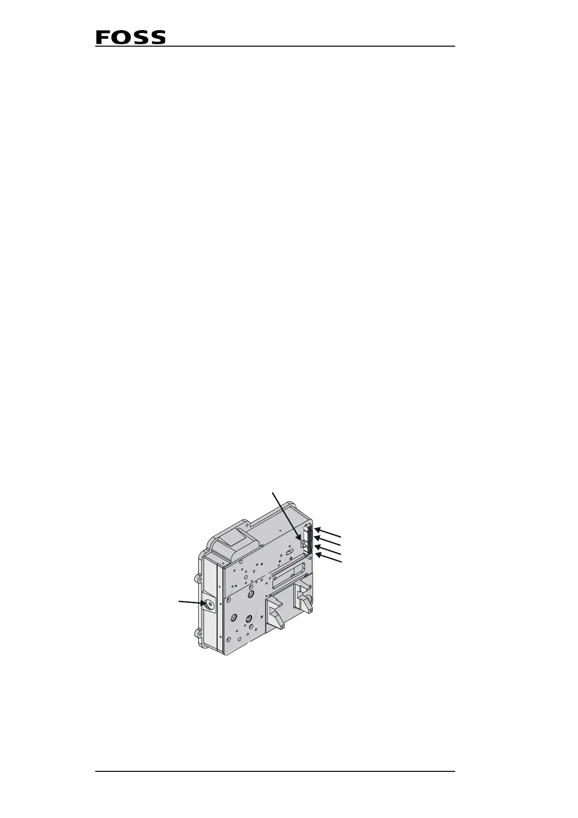
7. Disconnect the Drawer Sensor Cable (4), Speckle Emitter Cable (5) and any
Optional Equipment (2) or (3) connected to the Measuring Unit, see
Fig. 5:38
below.
8. Disconnect the Drawer Sensor itself from its placement on the Guide.
Fig. 5:38 Connections on the Measuring Unit
1241098a
1 Temperature sensor
2 Optional equipment
3 Optional equipment
4 Drawer sensor
6 Flush button
5 Speckle emitters
 Loading...
