Infratec™ 1241 Grain Analyzer
Service Manual 1001 5015 / Rev. 4 5:37
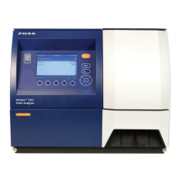
9. Loosen the Stop Screw to the Fibre Optic Cable Protector and slide it backwards,
see fig below.
Fig. 5:39 Stop screw (pos 5)
10. Now uncovered by the Protector, loosen the Stop Screw to the Fibre Optic Cable
itself and remove it from the Measuring Unit. Pull from inside the compartment.
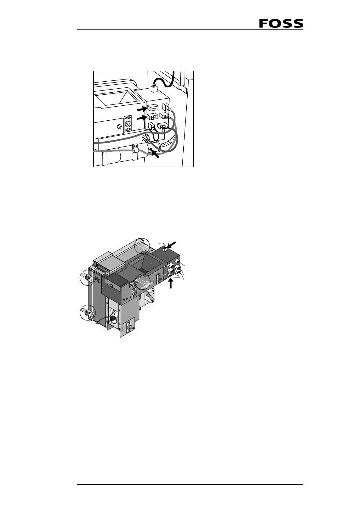
11. Loosen the four screws which fasten the Measuring Unit to the main chassis, see
fig below.
Fig. 5:40 Cables to disconnect on the MU
12. From inside the compartment: Slide the Measuring Unit off the hinge and
disconnect the cable from the Power Supply and the I
2
C cable from the DSP.
13. Exchange the Measuring Unit and install in reverse order.
3) Optional
4) Optional
5) Stop screw on protector
1) Drawer sensor cable
2) Ambient temperature sensor cable
 Loading...
