Infratec™ 1241 Grain Analyzer
Service Manual 1001 5015 / Rev. 4 4:23
the measuring unit when prompt for. Ten sub samples are taken and the 2
nd
peak is
detected and displayed on the screen.
Reference Scan
A reference scan is taken and the maximum level of the scan is displayed.
No software error indication on a scan level failure. The raw data values can be ex-
ported to disk by choosing the Disk option.
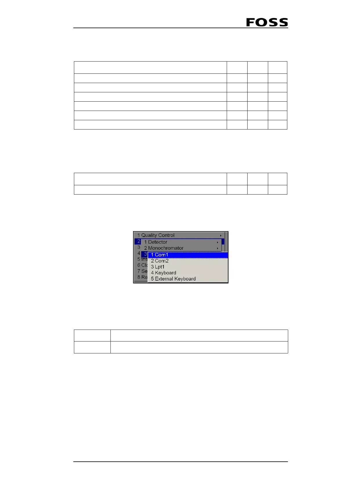
4.4.3 I/0 (Input/Output)
Fig. 4:10 Input/Output Tests
COM1 / COM2 / LPT1
It is possible to test communication ports and parallel ports by using loop-back con-
nectors.
For COM 1 and COM2 always make sure that you use the standard (Default)
settings for modem and serial line before starting this test.
This is changed in User Menu: Instrument settings → View → Communication →
Communication settings (1 Set Modem) (2 Set Serial). Choose “Default Modem
RS232“ in Set Modem. Restart the instrument before starting the loop-back test.
Choose “Default Direct RS232“ in Set Modem. Transmitted data values are
0x00-0xFF.
LPT1 One byte written and read back.
Line description including typical value Units Min. Max.
SelfTest/1241xxxx/Monoch./SerialNumber=String, T9010017
SelfTest/1241xxxx/Monoch./E/Peak2Mean=Number, 879.82 real
SelfTest/1241xxxx/Monoch./E/Peak2Min=Number, 879.61 real
SelfTest/1241xxxx/Monoch./E/Peak2Max=Number, 879.90 real
SelfTest/1241xxxx/Monoch./E/Peak2Std=Number, 0.02 real
SelfTest/1241xxxx/Monoch./E/Peak2Diff=Number, 0.07 real
Line description including typical value Units Min. Max.
SelfTest/00000000/Monoch./Ref/Max=Number, 56532 Bits 30000 65536
1001 0301 Loop-back connector Serial
1001 0302 Loop-back connector Parallel (printer)
 Loading...
