Infratec™ 1241 Grain Analyzer
2:6 Service Manual 1001 5015 / Rev. 4
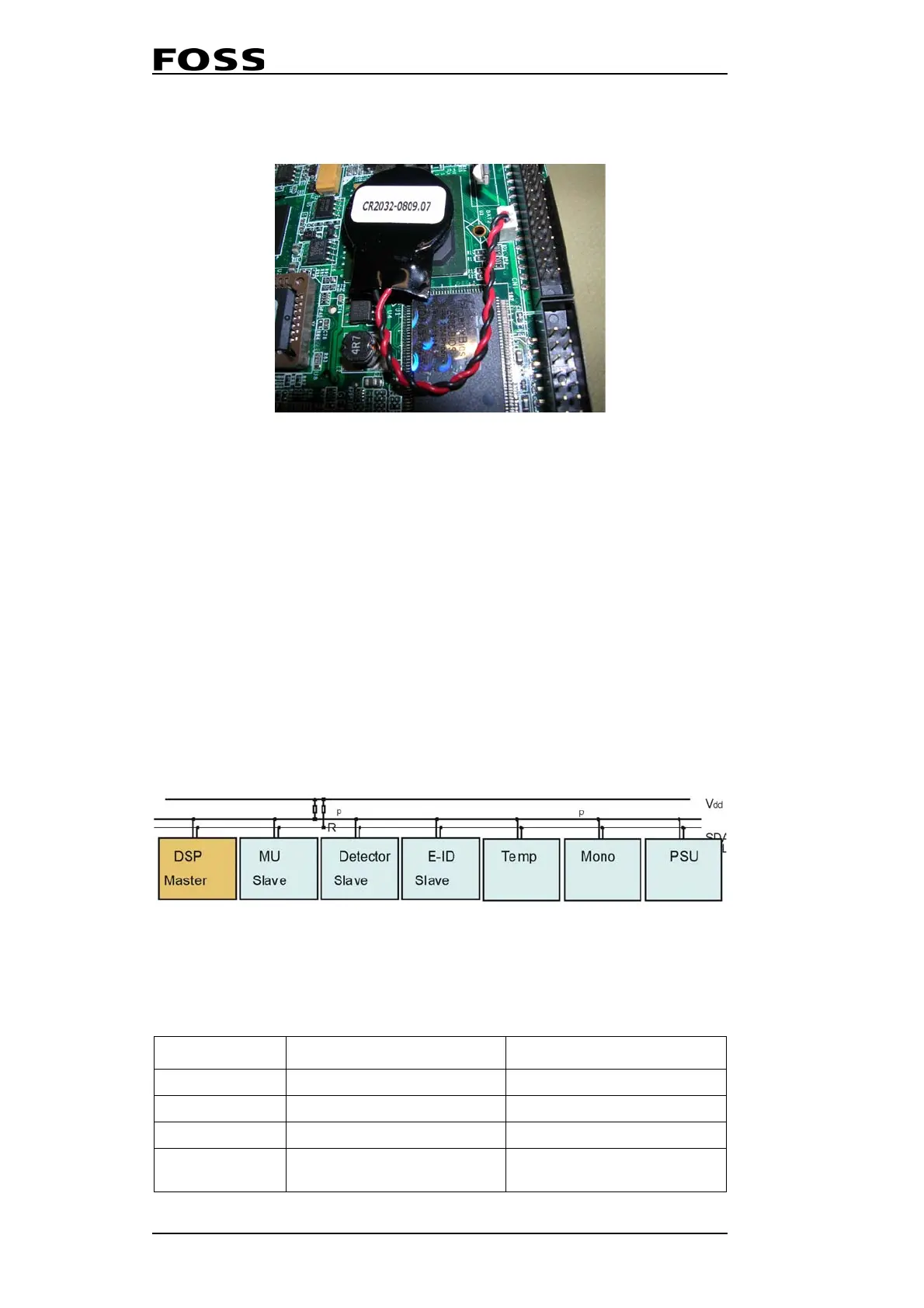
The Processor Board has replaceable external CMOS battery.
Fig. 2:4 Processor Board
2.2.3 DSP Board
The DSP module is accessed from the ISW via the PC/104 bus interface (P3) and acts
as slave under the ISW.
The DSP software acts as an extension of the ISW and is also used as an I/O system.
The PC-module makes it possible for the ISW to have control over the different HW
modules.
There is no ROM memory on the DSP Board. For this reason, the DSP software is
uploaded from the processor board by ISW during start-up. The ISW installation
package contains and installs the latest and matching DSP software version.
The DSP has an I
2
C bus interface, implemented as a SW driver in the DSP software
and is used for communication between devices inside the instrument. I
2
C is a two-
wire serial bus, as shown in
Fig. 2:5.
Fig. 2:5
There are a number of on board LEDs on the DSP Board. These LEDs provide
information as to the status of the DSP Board.
LED Function Color
D3 Power On Green, constant
D4 DSP-ISW communication Red, flashing when active
D1 DSP running Red, constant after boot-up
D2
Monochromator motor
direction
Red, blinking
 Loading...
