Infratec™ 1241 Grain Analyzer
2:20 Service Manual 1001 5015 / Rev. 4
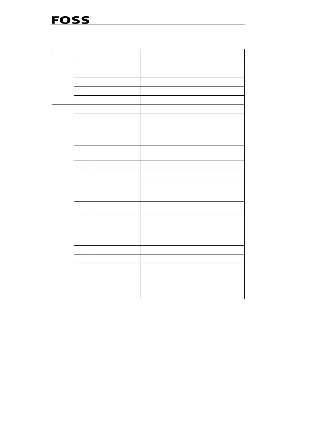
Pin description
Item Pin Name Description
I2C/
Power
1 SDA I²C Serial Data
2 SCL I²C Clock
3 GND
4 5V
5 12V
Sensor
1 12V 12V supply to external sensor
2 Trigger IN Trigger input used to start analysis
3 GND GND to external sensor
DSUB15
1 IO0 - Busy
Indicates that the Infratec 1241/1256 is busy
analysing
2 IO1 - Connected
Indicates that the Infratec 1241/1256 is con-
nected
3 IO7 - Trigger Trigger input used to start analysis
4 IO6 - Reserved Not used
5 GND
6 IO2 - AM Selection 0
Bit 0 of the 4 bit nibble used for selecting the
application model
7 IO3 - AM Selection 1
Bit 1 of the 4 bit nibble used for selecting the
application model
8 IO4 - AM Selection 2
Bit 2 of the 4 bit nibble used for selecting the
application model
9 IO5 - AM Selection 3
Bit 3 of the 4 bit nibble used for selecting the
application model
10 GND GND to external sensor
11 12V Output 12V supply to external sensor
12 NC NC
13 NC NC
14 NC NC
15 10-24V Input External power 10-24V for opto-couplers
 Loading...