Infratec™ 1241 Grain Analyzer
4:6 Service Manual 1001 5015 / Rev. 4
If the bus is corrupted in any way, the communication will not work. It is therefore
possible to have a black display, when the error is actually in the I2C communication.
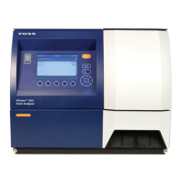
Fig. 4:1 I
2
C Communication
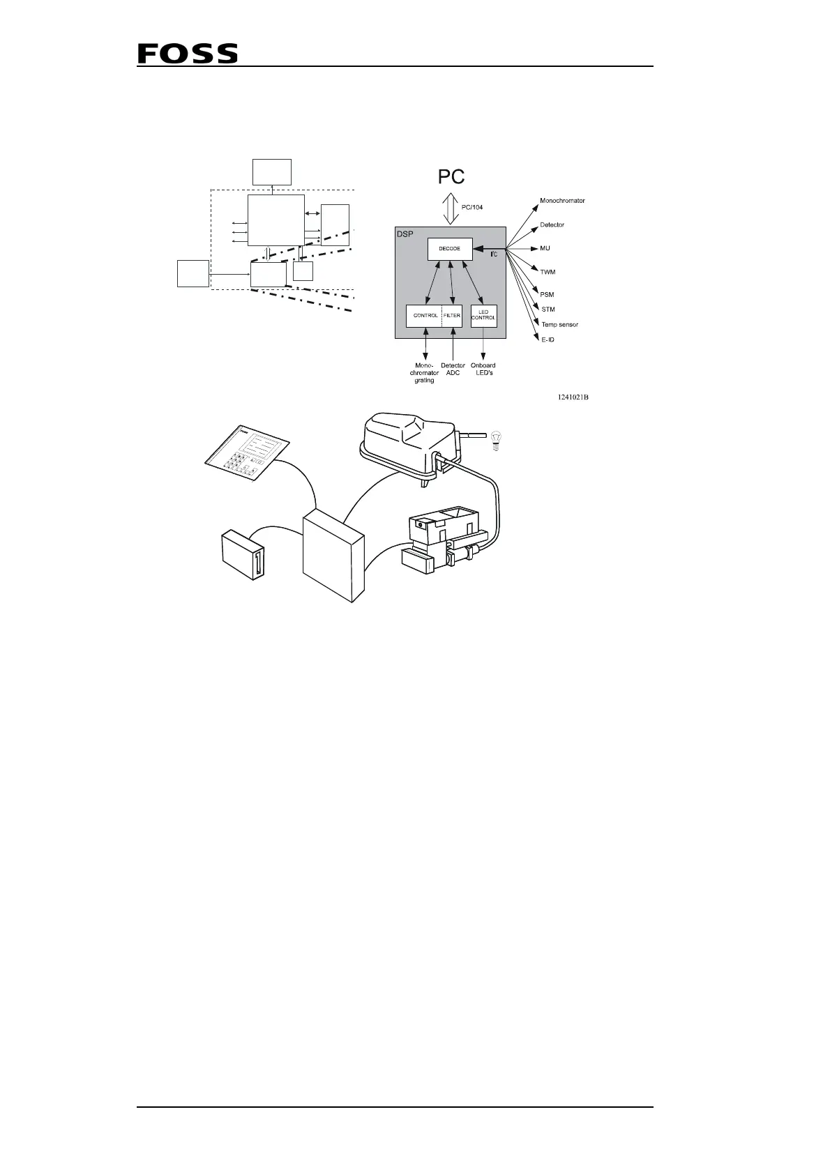
1 Lamp 7 Sample Cuvette
2 Lamp fiber (input) 8 Detector
3 Monochromator 9 PC Module
4 Output fiber 10 USB input/output
5 Measuring Unit 11 Keyboard
6 Conveyor Belt 12 Display
Processor
Module
PC/104
External PC
Modem
Printer
Com1
Com 2
LPT1
DSP
Module
Fan
Flash
disk
+5V
+12V
GND
GND
Display
Keypad
PROCESSOR MODULE BLOCK DIAGRAM
IDE
1241026a
+5V
DECODE
CONTROL
LED
CONTROL
Monochromator
Detector
MU
TWM
PSM
Onboard
LED's
Detector
ADC
Mono-
chromator
grating
DSP
1241021a
I
2
C
PC
PC/104
FILTER
STM
 Loading...