■
ETERNUS DX900 S5
Figure 45
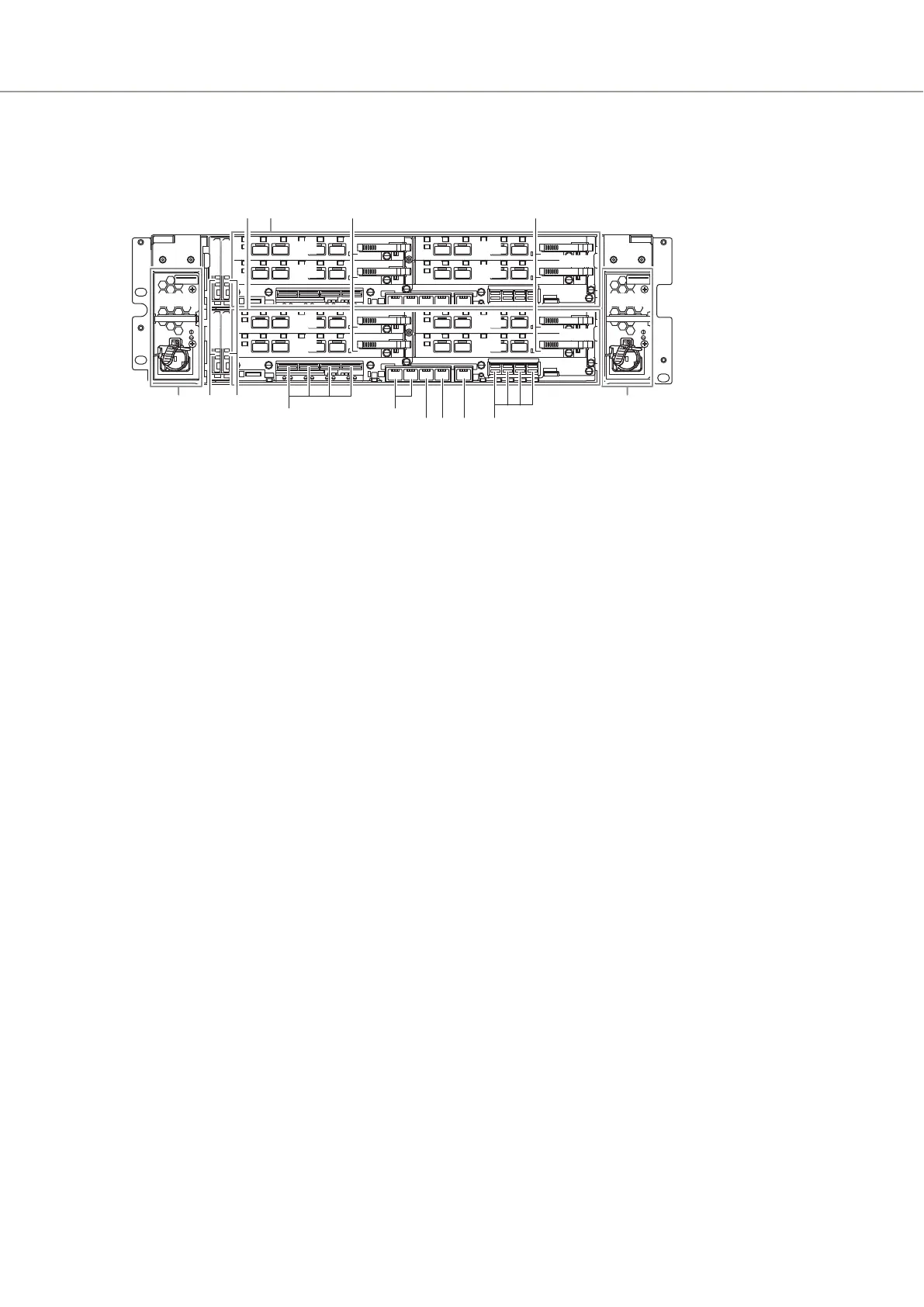
Rear View of a Controller Enclosure (ETERNUS DX900 S5)
9 9
1 1
5 643
10 10
7 8
CPSU#0
CPSU#1
CA#0
CA#1
CA#0
CA#1
CA#2
CA#3CA#2
CA#3
2 2
CM#0
CM#1
BUD#1
BUD#0
BUD#1
BUD#0
1 Controllers (CM#0, CM#1)
(Refer to "■ Controllers" (page 230).)
2 Host interfaces (CA#0, CA#1, CA#2, CA#3)
(Refer to "■ Host Interface" (page 237).)
3 RMT (LAN) port
This port is used for connecting a LAN cable and used for separating the network (such as for the remote
support) from the MNT port for operation management. This port uses an RJ-45 connector.
4 MNT (LAN) port
This port is used for connecting a LAN cable and used for operation management. This port uses an RJ-45
connector.
5 FST (LAN) port
A port that is dedicated for maintenance engineers. Customers must not use this port.
6 Drive interface (OUT) port
This port is used to connect a controller enclosure to a drive enclosure with a mini SAS HD cable between
enclosures.
7 FRT ports
This port is used to connect CMs and FRTs.
8 SVC ports
This port is used to connect CMs and SVCs.
9 Power supply units (CPSU#0, CPSU#1)
(Refer to "■ Power Supply Units" (page 235).)
10 BUD (BUD#0, BUD#1)
(Refer to "■ BUD" (page 242).)
A. Component Names
Controller Enclosure
225 Configuration Guide (Basic)
 Loading...