Chapter 2
Installation
29
SuperBus 2000 phone interface/voice module
The phone interface/voice module includes two backplates for mounting the module inside the control panel
cabinet. You may also mount the module outside of the cabinet using an optional plastic housing (part no. 60-
800). Refer to the documentation that comes with each module, for complete mounting instructions.
Note: In UL listed installations, the phone interface/voice module is for supplementary use only.
The module requires panel power and bus connections, phone line connection through panel terminals and
DB- 8 cord (from an RJ-31X jack), and speaker connection through panel terminals. Connect the module to the
panel power and bus terminals as shown in Figure 19.
For partition 1, connect the phone line to the module through the panel terminals and DB-8 cord (from an RJ-
31X jack) as shown in Figure 19 on page 29. For partitions 2 to 6 phone connections, see the documentation
that comes with each module.
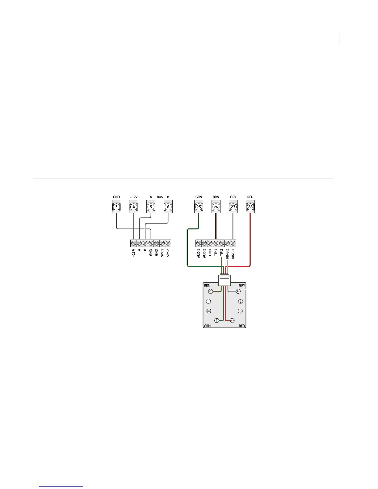
Figure 19. Wiring the phone interface/voice module
Note: To prevent status voice messages from being broadcast outside, do not connect exterior speakers to phone interface/
voice module terminals 6 and 7.
Module terminals
Panel terminals
RJ31X jack
DB-8 cord
 Loading...


