Concord 4
Installation Manual
30
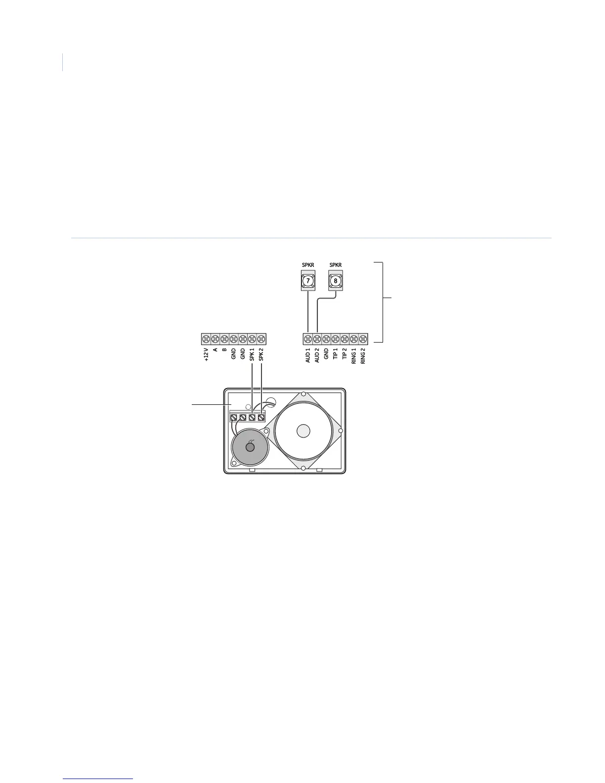
Wiring for status voice messages only
Connect an interior speaker to the phone interface/voice module terminals as shown in Figure 20. When
connected as shown, the speaker only produces status voice messages. In an alarm, the speaker announces
voice status messages.
Wiring for status and alarm messages
Make all of the connections shown in Figure 20 only if the phone interface/voice module is being installed in
partition 1 and alarm sounds are desired. In an alarm, the speaker alternates between alarm siren tones and
voice status messages.
Figure 20. Wiring the phone interface or voice module for status and alarm (or status only) messages
+12 V
A
B
GND
SPK 2
AUD 1
AUD 2
GND
TIP 1
TIP 2
RING 1
RING 2
GND
SPK 1
78
SPKR SPKR
Hardwired interior
speaker (60-528)
For alarm messages.
(For status only messages, do not
connect these panel terminals.)
Module terminals
Panel terminals
 Loading...


