Access control applications
3.40 EST3 Installation and Service Manual
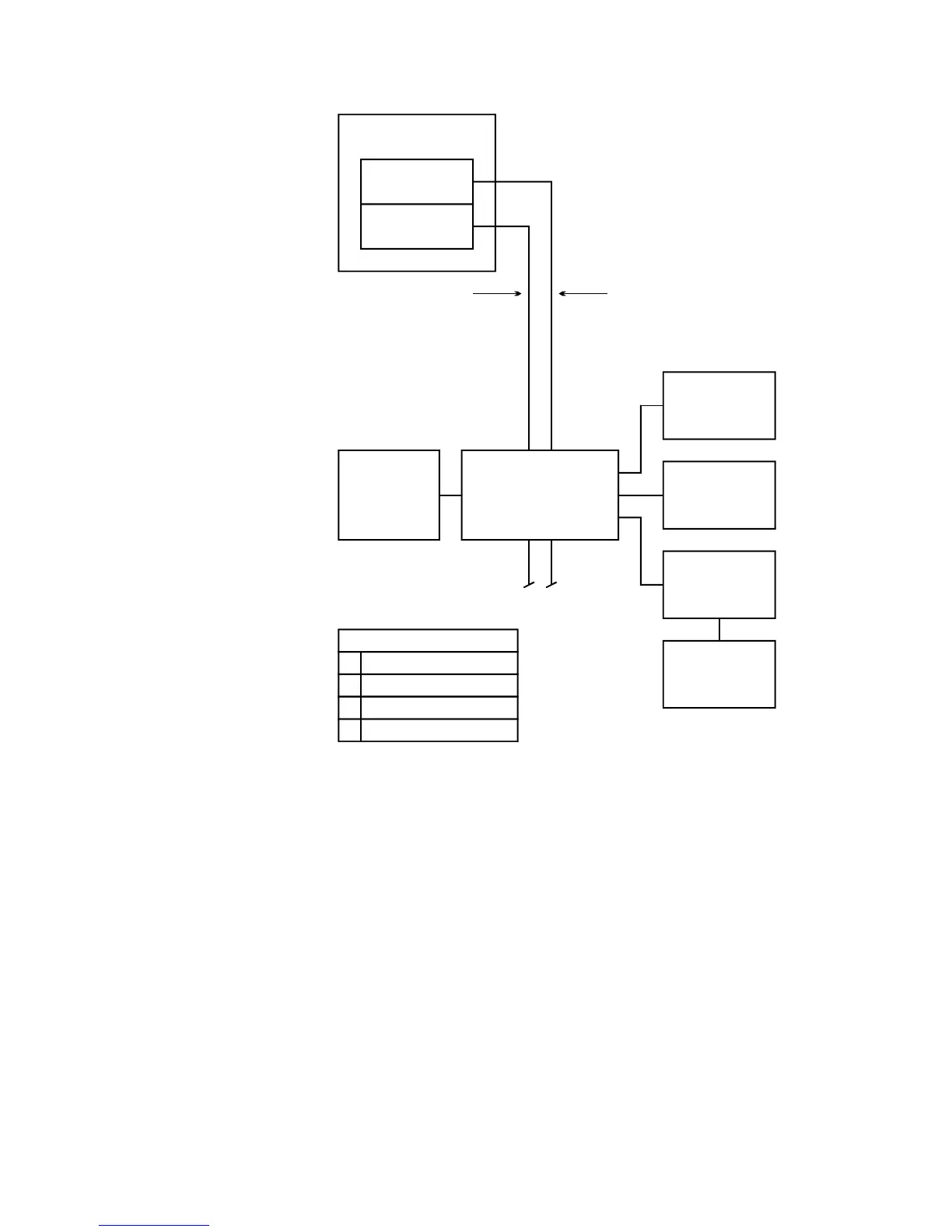
Control panel
3-SAC
3-PPS/M
Maglock
or strike
Card
reader
Power supply
Other factors
Hardware configuration
SDU programming
ACDB/KDC operation
X
X
X
CRCXF
Transformer
Passive
infrared
detector
SAC bus 24 Vdc connects to
CRC terminals, but
bypasses CRC
internally
Request to
exit button
CRC
Figure 3-14: CRC using AC power
The figure above shows the CRC power coming from the 16.5
Vac transformer. The 3-PPS/M power supply coming from the
control panel simply passes through the CRC. The 3-SAC
connects to the CRC through the SAC bus.
This wiring is shown in Figure 3-15.