Access control applications
EST3 Installation and Service Manual 3.41
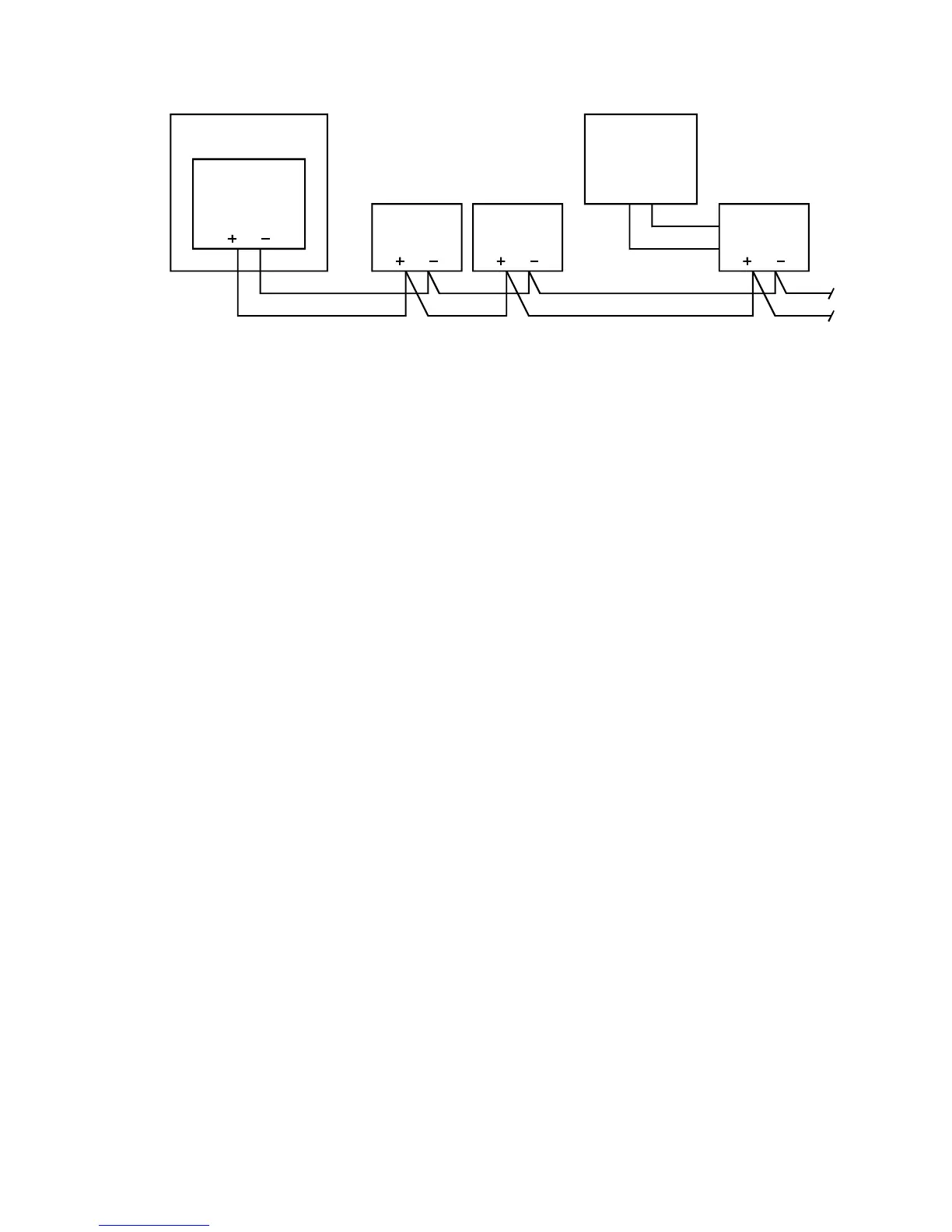
Control panel
Power supply
24 Vdc
CRCXF
Transformer
(16.5 Vac)
CRC
24 Vdc
CRC
24 Vdc
CRC
24 Vdc
Figure 3-15: Wiring details for transformer supply
Power supply
Jumper settings determine the power source and usage for the
CRC. Configure the input power as AC. Configure the output
power as continuous.
If you use an additional power supply other than the CRCXF,
that power supply must be listed for fire alarm applications, must
have ground fault detection disabled, and must have a circuit
ground (circuit common) that is isolated from earth ground.
Hardware configuration
The control panel must contain the following rail modules:
• 3-SAC Security Access Control module
• 3-PPS/M Primary Power Supply module
The 3-SAC module supports the SAC bus. Power for the CRC is
normally taken from the 3-PPS/M and is routed with the data
lines in a cable composed of two twisted-pair wires. In this case
the power from the 3-PPS/M is connected to the CRC terminals,
but internally bypassed.
The 16.5 Vac transformer should be plugged into a continuously
energized AC socket, not one controlled by a switch.
SDU programming
When programming the system for this application, you’ll need
to configure the CRC and define the appropriate lock type in the
SDU. This can be either a strike or maglock.