Access control applications
EST3 Installation and Service Manual 3.43
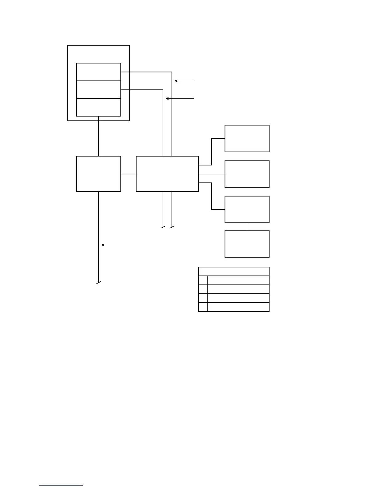
Control panel
Signature
Controller
3-PPS/M
3-SAC
CRC
Maglock
or strike
Card
reader
Power supply
Other factors
Hardware configuration
SDU programming
ACDB/KDC operation
X
X
X
Remote
power
supply
24 Vdc
Passive
infrared
detector
SAC bus
+24 Vdc bypasses CRC
SIGA loop monitors remote
power supply
Request to
exit button
Figure 3-16: CRC using remote power
The negative side of the 3-PPS/M power supply coming from the
control panel connects to the CRC (and to all other CRCs). The
positive side is broken and the remote power supply picks up the
load. This wiring is shown in Figure 3-17.