Access control applications
3.44 EST3 Installation and Service Manual
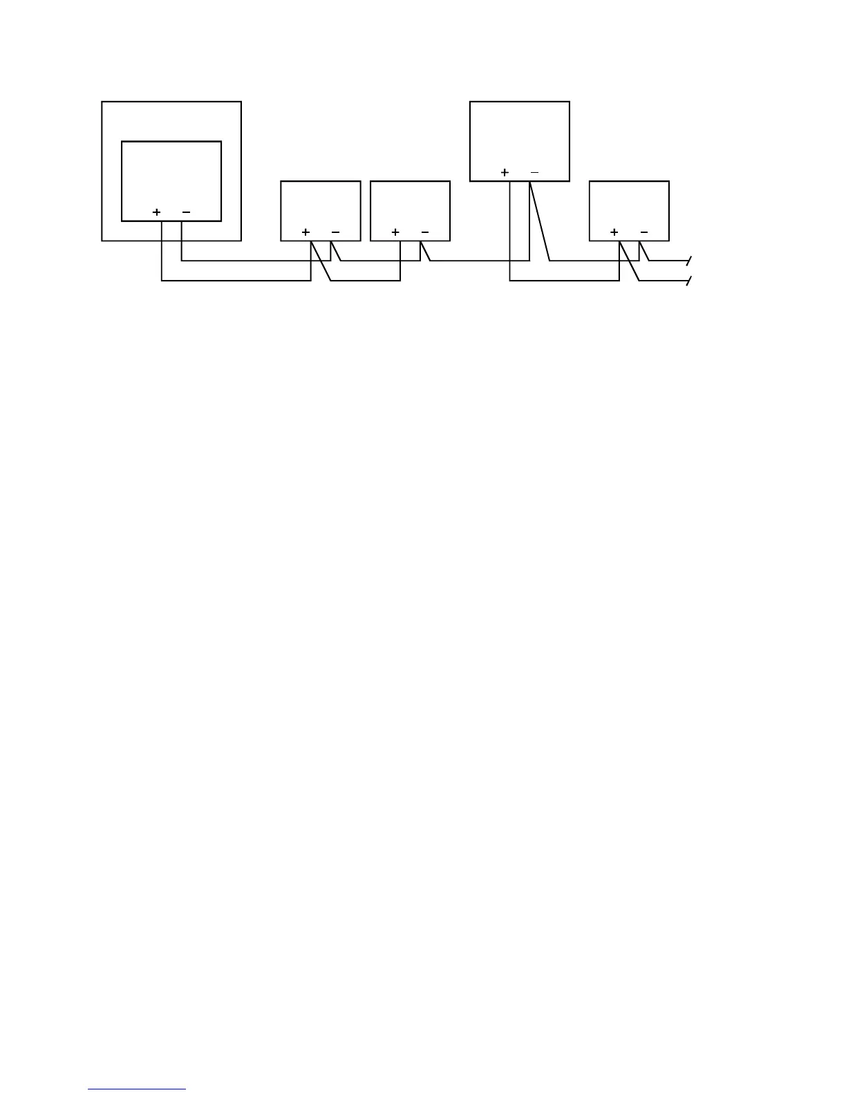
Control panel
Power supply
24 Vdc
Remote
power supply
CRC
24 Vdc
CRC
24 Vdc
CRC
24 Vdc
24 Vdc
Figure 3-17: Wiring for remote power supply
Power supply
Jumper settings determine the power source and usage for the
CRC. Configure the input power as DC. Configure the output
power as continuous.
Note that additional power supplies must be listed for fire alarm
applications, must have ground fault detection disabled, and
must have a circuit ground that is isolated from earth ground.
Hardware configuration
The control panel must contain the following rail modules:
• 3-SSDC(1) Single Signature Controller module
• 3-SAC Security Access Control module
• 3-PPS/M Primary Power Supply module
The 3-SSDC(1) module supports the SIGA loop, which
supervises the remote power supply
The 3-SAC module supports the SAC bus. Power for the CRC is
normally taken from the 3-PPS/M and is routed with the data
lines in a cable composed of two twisted-pair wires. In this case
the power from the 3-PPS/M is simply passed through the CRC.
The remote power supply is supervised by the 3-SSDC(1)
module via the Signature loop. The remote power supply must
share a common ground with the 3-PPS/M.
SDU programming
When programming the system for this application, you’ll need
to configure the CRC and define the appropriate lock type in the
SDU. This can be either a strike or maglock.