Centralized audio applications
4.18 EST3 Installation and Service Manual
Do Not Use
Do Not Use
FUSE 2 5 A
24 VDC
BRID G I N G
INPUT
COM
70.7 V
25 V
8 OHM
OUTPUT
COM
25 V
CT
EA R TH
N/C
LEVEL ADJUST
FUSE 6. 2 5 A SB
120VAC
60HZ
TO ATP
PO WER REC EPTACLE
AUDIO
RI SER
OUT
+
G
N
H
TB 4
120VAC
60HZ
10A M AX.
TB 5
FUSE
3AB-20A
TB 2
OUT
S+
+
+++ ++SSSS
TB 1
TB 3
PO W ER
FA I L
PA N EL
TRBL
ACTIVITY
AMP # 1
AMP # 2
PREAM P # 2
PREAM P # 1
PWR AM P # 2
PWR AM P # 1
BATT.
OUT
BATT.
OUT
BATT. IN
24 VDC
40AH MAX.
120 VAC OUT
WARNI NG
FOR C O NTI NUED PRO TEC TI ON
AGAINST TH E RI SK O F FI RE,
REPLA C E O N LY WI TH SA M E
TYPE 8 RATIN G FUSE.
IN
IN IN
INOUT
OUT OUT OUT
OUT
S+ ++ + ++SSSS
[3ATPI N T6.CDR
IN
IN
P1
PREAMP 1
70V 25 V
PREAMP 2
70V 25 V
1
1
P2
OUT RISER
OUT RISER
OUT PRE-AMP
OUT PRE-AMP
PRE-AMP 1
PRE-AMP 2
+ - S + - S + - S
+ - S + - S + - S
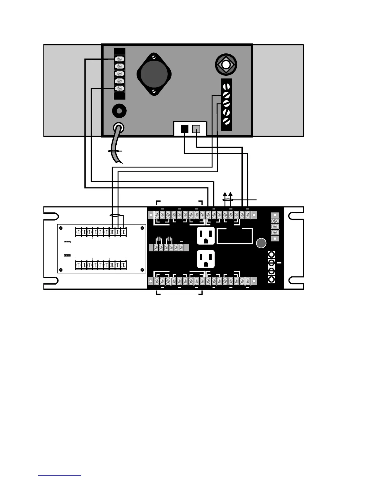
AMPLIFIER TERMINAL PANEL (ATP) P/ N 2 4 0 0 6 8
3-ATPINT
Figure 4-10: Wiring from Dukane amplifier to ATP