Installation
EST3 Installation and Service Manual
5.10
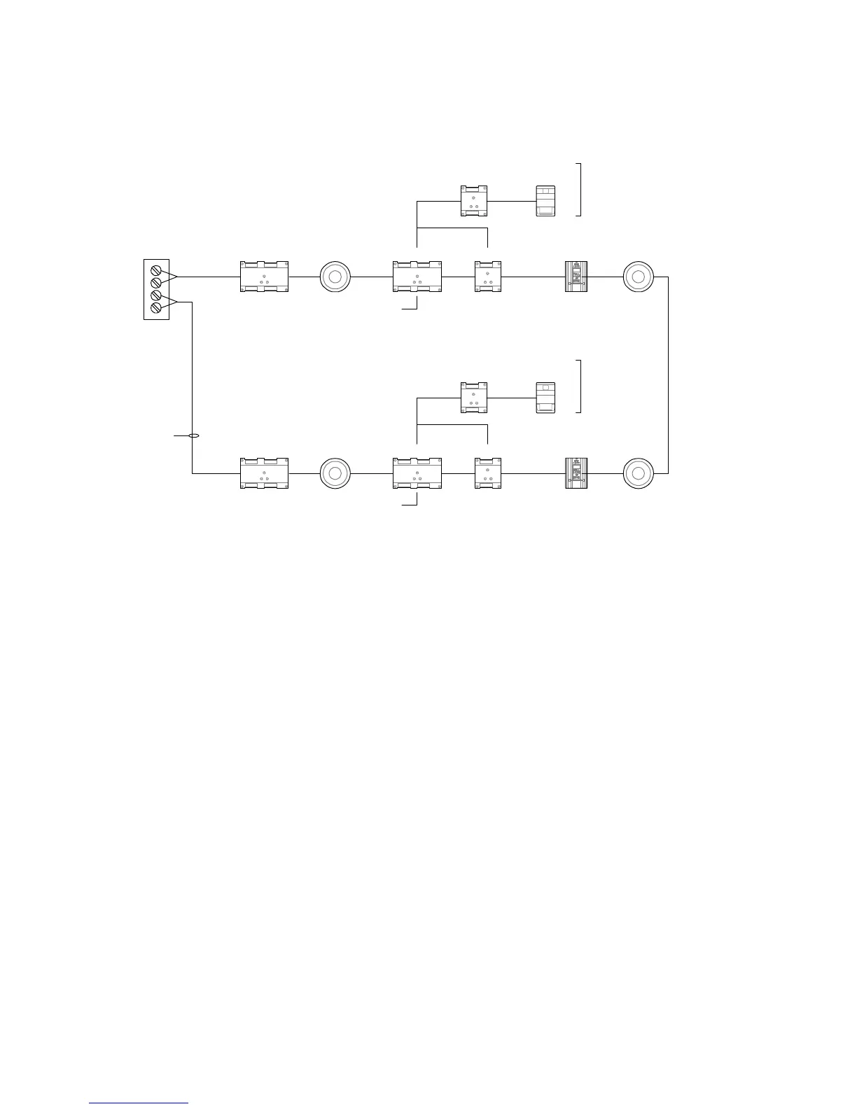
Figure 5-2 shows a Signature circuit, wired as Class A, and using
isolation modules or bases for each IDC and NAC.
IM
IM
SIGA B+
SIGA B–
SIGA A+
SIGA A–
Class A
(required)
Isolater
base
Isolater
base
IPHS
IPHS
270
270
CC1
CC1
CR
CR
IPHS
IPHS
AUX riser
AUX riser
Notification
zone 1
Notification
zone 2
Temporal
horn/strobe
Temporal
horn/strobe
Sync
module
Sync
module
Figure 5-2: Signature wiring for notification circuit signal synchronization
Figure 5-3 Shows two NACs on a Signature data circuit. Each
NAC is controlled by a SIGA-CC1S module, one for audible
appliances, and one for visible appliances.
As in Figure 5-1, this configuration allows the audible appliances
to be silenced independently of the visible appliances. This
operation is optional, and may or may not be required for your
project.
The SIGA-CC1S modules provide signal synchronization for
both NACs.