Service and troubleshooting
8.10 EST3 Installation and Service Manual
network communication between CPU modules in other cabinets
is also processed by the CPU. Network communication is
RS-485 when the 3-RS485 card is installed in CPU connector J2,
and fiber optic when the 3-FIBMB or 3-NSHM module is
connected to J2 of the CPU.
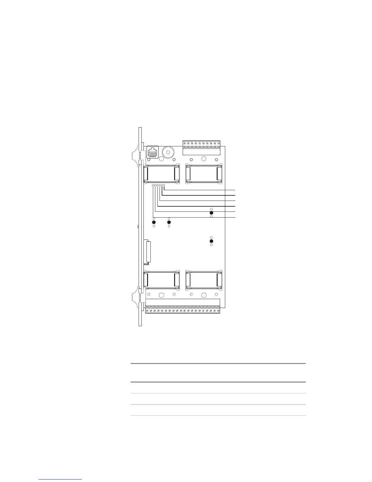
Network and audio data circuits
Figure 8-1 and Table 8-4 show the location and normal state of
the communication status LEDs on the CPU module.
TB1
SUP
C
LARMTROUBLE
O
N
C
NC
O
NC
-
A
C
NN
O
N
C
N
NETWORK
+
B
+
AA
-
AUDIOAUDIO
B
-+
A IN A OUT
+--
R
X
111
T
X
R
T
S
2122
C
X
O
M
R
R
T
X
T
S
2
C
O
M
IN
OUT
B OUT
AUDIO
++
AUDIO
B IN
--
J1
Rx1
Rx2
Rx3
Tx1
Tx2
Tx3
[CPULEDS.CDR]
Figure 8-1: CPU module
Table 8-4: CPU LED indications
LED Normal
state
Description
RX1 Flicker Local Rail Receive Activity
TX1 Flicker Local Rail Transmit Activity
RX2 Flicker Network Data Ch A Receive Activity
TX2 Flicker Network Data Ch A Transmit Activity