Service and troubleshooting
EST3 Installation and Service Manual 8.11
RX3 Flicker Network Data Ch B Receive Activity
TX3 Flicker Network Data Ch B Transmit Activity
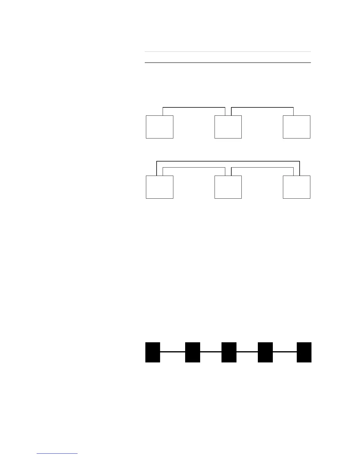
EST3 network wiring alternates between channel A and channel
B, as shown in Figure 8-2.
A B
CPU
Class B network siring one-line diagram
Class A network wiring one-line diagram
A B
CPU
A B
CPU
A B
CPU
A B
CPU
A B
CPU
Figure 8-2: Network wiring one-line diagrams
RX1 and TX1 should flicker continuously, indicating normal
two-way CPU module to rail module communication activity.
When multiple CPU modules are networked together using Class
B wiring, RX2, TX2, RX3, and TX3 on all panels except the first
and last should flicker continuously, indicating normal two-way
network communication activity on both data channels.
When multiple CPU modules are networked together using Class
A wiring, RX2, TX2, RX3, and TX3 should flicker continuously,
indicating normal two way network communication activity on
data channels A, and B.
The network and audio riser data circuits are isolated at each
CPU module. This prevents a shorted data circuit from
interrupting communication on the entire circuit. Figure 8-3
shows typical Class B network data circuit.
NETT
1.
DR
1 2 3 4 5
Figure 8-3: Class B network data circuit