Service and troubleshooting
8.22 EST3 Installation and Service Manual
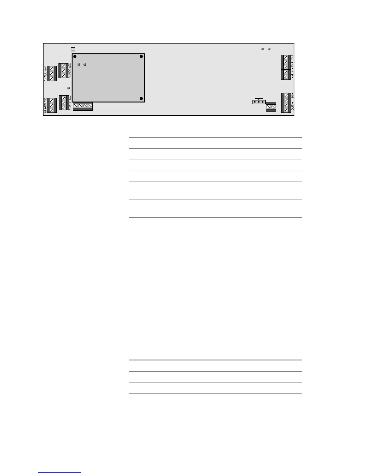
[3SIGAMP1.CDR]
TB4
DS3 DS2
TB5
TB6
25V
70V
+ 24V -
JP2
BACKUP
NAC
TB3
TB1-IN
TB1-OUT
TB2-IN
TB2-OUT
DS5 DS4
DS1
SIGA +IN- +OUT-
Table 8-15: SIGA-AAxx LED indications
LED Color Description
DS1 Yellow Power Amp Enabled
DS2 Yellow Backup Mode
DS3 Green Amplifier Active
DS4
(daughter board)
Green (flashing) Normal
DS5
(daughter board)
Red (flashing) Active Condition
Gain adjustment
With the amplifier connected to the speaker load, use the gain
adjust potentiometer (R116) to get a 25 Vrms or 70 Vrms signal
(depending on JP2 setting) with a 1Vrms
1 kHz tone at the
amplifier input. If a oscilloscope is used to adjust levels, use the
following peak-to-peak voltage levels:
• 25 Vrms = 71V
PP
• 70 Vrms = 200 V
PP
The amplifier must be connected to a load to properly adjust the
gain. In the event the actual speaker circuit can not be used, a
dummy load must be fabricated according to Table 8-16. The
wattage rating of the dummy load must exceed the output power
rating of the amplifier.
Table 8-16: Amplifier dummy load values
Output power 25 Vrms output 70 Vrms output
30 Watts 20.8 Ω @ 30W 167Ω @ 30W
50 Watts 12.5 Ω @ 50W 100Ω @ 50W
To maintain DC supervision and keep the amplifier out of
trouble while adjusting the gain, connect a 47 kΩ EOL resistor