Service and troubleshooting
8.58 EST3 Installation and Service Manual
[TSCRN3.CDR
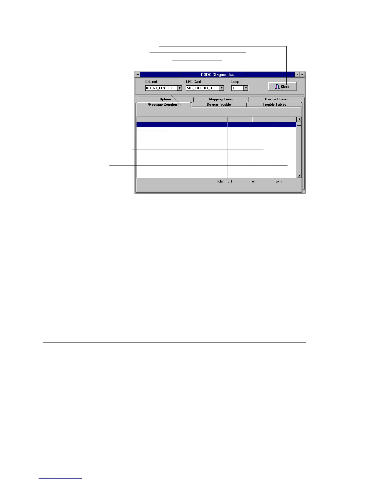
Message Counters Tab
Message
Total Messages Sent
Incorrect Message Count
Percentage of
Valid Messages
Click Here
to Select Cabinet
Click Here to Select Loop Controller Card
Click Here to Select SDC Circuit
Click He
e to Close LPC Diagnostics
Figure 8-19: Message counters dialog box
The message command appears in the left column, followed by
the number of times it has been issued, the number of errors
received after the message was issued, and the percentage of
correct responses. During normal operation, the percentage of
messages received correctly should exceed 99%.
Intermittent device or wiring problems are indicated by a low
successful message rate. If successful message rates are tracked
over time, one can generate base line information for each
circuit. From the base line information, any changes from the
norm can be quickly identified, and preventive measures taken,
before a communication problem develops. Table 8-36 lists the
messages sent and received by the Signature driver controller
module.
Table 8-36: Signature controller module Internal Messages
Query End Of Line Query Relay Status Find New Start
Query Isolator Ground Fault Check Find New Active
Query Status Query Device Mask Find New Unused2
Pulse Visible LED Query Group Mask Find New Unused3
Query Map Result Module PFX Reset Device
Query Alarm Status Query Ready Comm Enable Device
Query PreAlarm Status Find Serial Number Disable Device
Query Normal Status Find New Alarm Start Device