System overview
1.38 EST3 Installation and Service Manual
General channels have a lower priority than the Alert channel.
The alarm silence function does not automatically silence the
Alert channel unless programmed to do so.
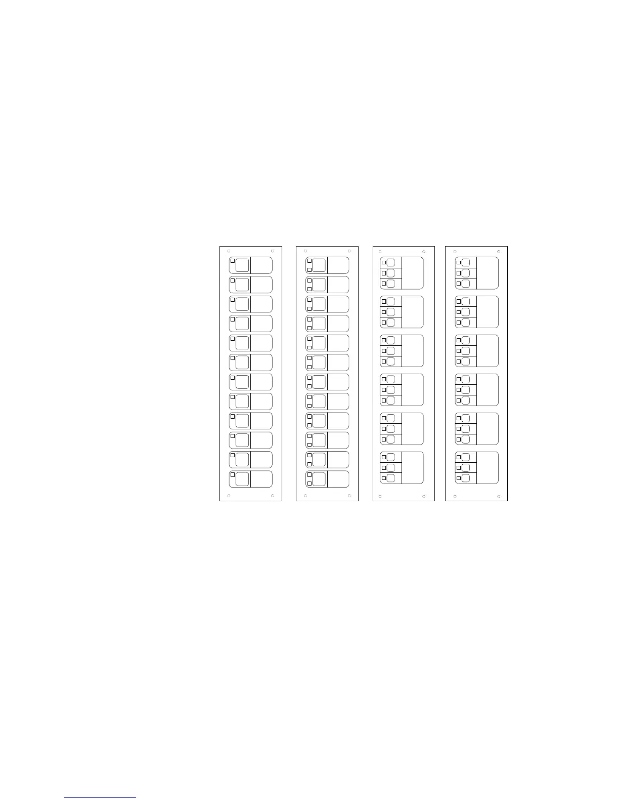
Manual audio zone selection
If manual audio zone selection is required on the system, the
appropriate control/display modules must be mounted on
modules in the same cabinet as the Audio Source Unit. Typical
configurations of control/display modules is shown in Figure
1-18. Exact operation of each display is dependent on system
programming. Typical operation is described below.
1
s
t
F
l
o
o
r
2
n
d
F
l
o
o
r
3
r
d
F
l
o
o
r
4
t
h
F
l
o
o
r
5
t
h
F
l
o
o
r
6
t
h
F
l
o
o
r
ABCD
Pa g e
12t h Fl
Page
11t h Fl
Page
10th Fl
Page
9th Fl
Page
8th Fl
Page
7th Fl
Page
6th Fl
Page
5th Fl
Page
4th Fl
Page
3rd Fl
Page
2nd Fl
Page
1st Fl
Page
12th Fl
Page
11t h Fl
Page
10th Fl
Page
9th Fl
Page
8th Fl
Page
7th Fl
Page
6th Fl
Page
5th Fl
Page
4th Fl
Page
3rd Fl
Page
2nd Fl
Page
1st Fl
Alert
Evac
Page
Alert
Evac
Page
Alert
Evac
Page
Alert
Evac
Page
Alert
Evac
Page
Alert
Evac
Page
1
s
t
F
l
o
o
r
2
n
d
F
l
o
o
r
3
r
d
F
l
o
o
r
4
t
h
F
l
o
o
r
5
t
h
F
l
o
o
r
6
t
h
F
l
o
o
r
Alert
Status
Page
Alert
Status
Page
Alert
Status
Page
Alert
Status
Page
Alert
Status
Page
Alert
Status
Page
Figure 1-18: Audio zone selection displays
Display A is a model 3-12SG. Each floor switch provides audio
zone selection for the Page signal, and the integral green LED
indicates the audio zone is selected.
Display B is a model 3-12GY. Each floor switch provides Page
audio zone selection. The green LED to the upper left of the
switch indicates the audio zone is selected. The yellow LED to
the lower left of the switch indicates audio circuit trouble.