2018112-069 Rev. F eBike II, eBike II L, eBike II EL - 125 -
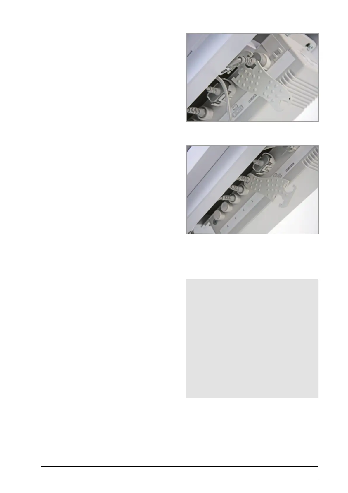
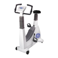
• Place the special tool onto the power connector and
unlatch the clamps by pressing the tool downwards.
• Disconnect the power connector.
• Disconnect the remote control cable connector the
same way.
• The other side of the tool is used to unlatch the
connectors of the motor cables (marked 1, 2 and 3) by
turning the connector (bayonet xing) and pulling out.
• Loose the xing screws of the motor control unit.
• Assembly of the new control unit is performed in
reverse order.
Hint
• Do not interchange the motor connectors!
(Cable and jacks are marked !)
• Following the exchange of a motor or after any malfunc-
tion the control unit has to be initialised!
To initialise the control unit, both motors have to be
moved in dened end positions::
- The motor for the supine angle has to be retracted
completely (supine horizontal)
-- The motor for the supine angle has to be extended
completely (supine 45° to the side)