- 14 - eBike II, eBike II L, eBike II EL 2018112-069 Rev. F
eleCtronIC Modules / asseMBly
overvIew
desCrIptIon of eleCtronIC and CaBlIng
The electronic of the eBike II is based on a modular
concept.
Each module has its own processor with the appropriate
software.
To communicate between dierent modules, the CAN bus
is used - a stable and standardized protocol used in the
automotive industrie.
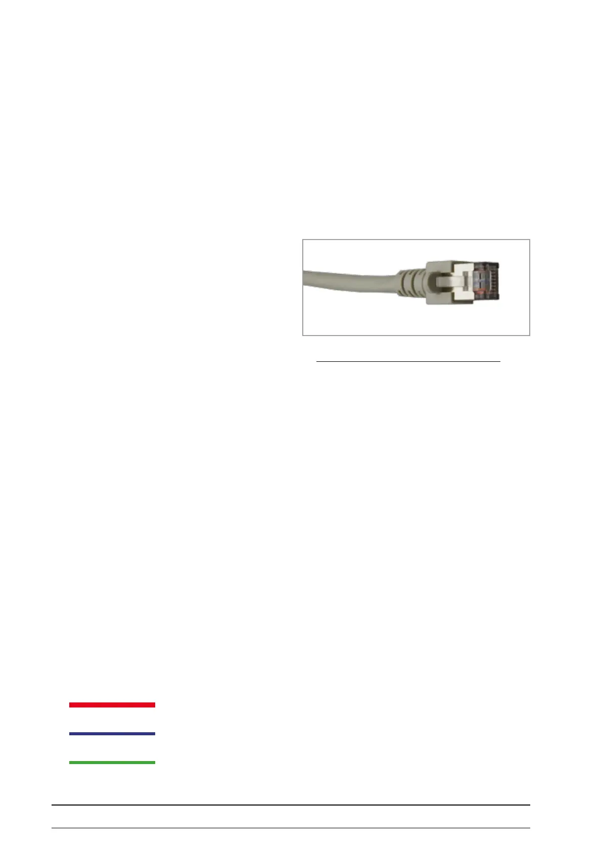
The connection between dierent modules is made by use
of standard shielded patch cables.
These cables carry the power lines (24 volt) and the CAN
bus signal lines.
aBBrevIatIons
ZME Main control unit
LRE Load regulation unit
BKE Basic communication unit
BDE Bloodpressure unit
PNE Pneumatic unit (NIBP)
MAE Saddle motor unit
DMS Strain gauge
LCD Display
Standard connecting cablel (patch cable, Shielded)
RJ-45 Patchcable
Microfone cable
Connecting tube (cu)